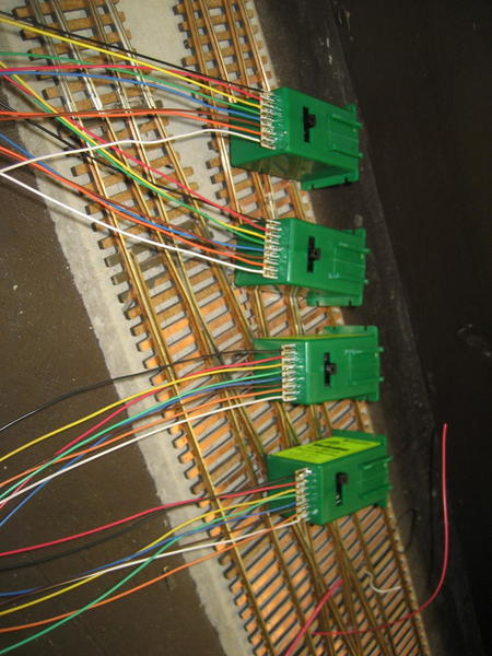
I am working on a storage yard built with several Old Pullman switches and controlling same with Tortoise machines. Problem -- I just do not seem to get enough throw .... I have changed wire sizes and played with the adjustment, Is the the design of the switch with "bending" the rail my problem and is there a better way to move the switch? Thanks, Bruce in Mount Airy, MD
Replies sorted oldest to newest
The Tortoise is not the problem. The adjustment part that slides up and down. Seems to have more of an affect on the tension. The throw is limited to the size of the hole. I believe they recommend a 1/4 inch hole. I have had to elongate most of mine to get enough throw. The thickness of your Benchwork also will limit the throw.
BTW --- using 3/4 plywood with 1/4 cork roadbed and 3/8 holes slightly elongated with wood file rod does not touch wood.
I agree with Dave C. My layout is 1-3/4" thick. I needed a1/2" hole to operate lionel post war O/72 switches. They work great. I did have to upsize the diameter of the wire due to my increased layout thickness. The lower the fulcrum (sliding bar)is moved down, the wider the throw of the wire. Slide it up and the throw narrows. Be sure the throw bar of the track switch moves freely with little to no resistance as the supplied wire will flex reducing the overall throw. Make sure to center the throw of the track switch and drill directly below that center.
The wire Tortise supplies is too small for many 0 scale throws. I find drilling out the hole and replacing the wire with several sizes larger/stiffer works like a charm.
Rail joiner connected points are a bit easier to throw but the solid frog to point rails will not respond properly with the factory Tortise supplied wire.
IMO, that is the ONLY draw back to that switch machine. I use them a lot. Great for double cross overs and diamonds. No aux. relays needed. All frogs live.
I cut a 1/4" by 1" slot under all throws.
3/4" Birch and 1/2" Homosote further strains the small wire.
Also, I find carefully soldering the wires directly is better than using the pressure fit terminal strip.
Attachments
Tortoise use.022 wire Fast Tracks say .037, I use .040 wire I don't like soldering wires direct to the motor I use plugs that way if there is a problem you just have to unplug the machine.
I have at least 60 tortoise machines on the layout some are many years old.
Roo.
Attachments
Bruce,
- use spring wire and just slightly larger than .025"
- include the 15 degree bend in the spring wire
- verify the larger openings of the tapered pivot holes (in the fulcrum) face the bottom
If your points are not hinged there will not be enough torsion in the throw wire. Use a Dremel with a cutoff disk to cut *UP* from the base through the rail where you want it to bend. Do not cut all the way up through the rail just the base and some of the web. This will make the rail much easier to bend.
If you have hinged your points I don't know what is causing the problem.
I use .039" music wire with no problems. Over 60 Tortoises.
Roo, I plead guilty to overthinking things. Just not a fan of potential plug resistance.
However I do run all my Tortoise leads to a 8 port terminal strip. That way the switch machine is some what easy to remove. Any wire connection could be a point of resistance but I prefer the option to determine the crimp pressure or the screw torque.
The simplicity of Tortoise plug connections have tempted me more than once.
Attachments
Hi Tom.
There are many ways to do things. The BRHRR has been improved and updated many times over 30 years the mention of wire above I forgot to say piano wire which I thought would be obvious you wouldn't use soft wire.
I have a very reliable Railroad I am never frighten to have visitors nothing goes wrong we have a session, everything works the way it should, what I mention on forums is the result of many years in O scale and what I mention is what we have found over those years that suits us.
There are 75 +turnouts on the layout the real older one's are still being operated by solenoids just recently I have added a Steel mill (buildings still under construction) to the layout there are 22 turnouts all worked by Tortoise machines I sat underneath lining the wire up while my wife or anyone around held it till I screwed the machine to the base I don't use a jig I drill one hole from the top to get a bearing underneath 3 weeks later it's a joy to operate all the turnouts work and the trains appreciate the track laying even have a three way curved turnout amongst the trackwork.
I stress that my base is not thick it's 15mm (5/8ths) and I find I need a 3/8th hole for the wire I'm very careful laying the turnout in the centre of the hole where the wire goes through my turnouts are copper clad from Marcway in England and the vary in size from 36"radius to 48" radius the rails are not hinged and have found nothing has come loose after 7 years of operation a very reliable turnout.
There are many ways to do things find the one that works for you and stick with it till a better idea comes along.
Roo.
Like the others, I changed to heavier piano wire and included the proper bends to it and have 40 or so on the layout without an issue. Most are Old Pullman turnouts that bend the rail like you mention, 3/4" plywood, and half inch roadbed. Adjusting the slider along the outside of the machine helps.
Update: So I've spent a lot of time checking and rechecking anything & every thing that has been mentioned and what I have done. I installed an Atlas O switch with the tortoise and it works flawlessly. So to get back to my Old Pullman dilemma, I have six Old Pullman number fours, all of them are non-hinged point turnouts. This I believe is my problem - I have found that the tortoise switch machines do not throw completely even with the O.39 wire I'm using - if I disconnect the solid point rails the tortoise machine throws all the way so I believe that they just cannot handle the code 148 rail even though it is cut at least 5/8 of the way up the web of the rail. For now my choice is - do I make these into hinged point turnouts ? If anybody's has experience in doing that I'd love to hear about it. One of the challenges of this is that these six switches are already installed on the layout. Other choice would be to replace all six but I know of no commercially available number four. So does that mean hand laying? I do have some fast tracks items somewhere that would help speed that process. Please help. Thanks in advance
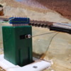
Bruce Not familiar with the pullman but, I had a similar problem with to much flex in the .039 piano wire I used. My issue was locations where I had 2" + of layout depth. I configured the tortoise inverted on the top of the layout(see pic) this allowed a push/pull of the throw. Little to no flex. Notice the small loop in the wire at the tortoise to compensate for length of the throw and allow the wire to pivot through the arc of the tortoise throw arm without binding. I slipped a trimmed to fit light switch cover plate over the tortoise which allowed firm mounting through 1" foam the 3/4" ply below. In the other instance I cut out a square of the 1" foam to recess the tortoise making the throw wire parallel with the track switch. Constructing balsa switch shantys to slip over and conceal these.
Attachments
Thanks for the input .... mis-typed the spring wire size, I worked my way up and seem to have the best results with 0.47 --- still not getting the throw. Less than 1 inch thru the plywood, cork and ties. Bruce in Mount Airy, MD
I had similar issues with a couple of code 148 Old Pullmans, admittedly # 5, not 4, so the longer switch points are a bit bendier I expect. But after I did all the things various people mentioned above, up to 0.47 wire and the fulcrum slider turned upside down and slid down to the very bottom and glued in place etc., still not quite enough throw though 3/4" ply plus cork.
Then it hit me: The switch points had been soldered too close together on the tie bar meaning the required throw was too much. When I checked the points to stock rail flangeways with my NMRA gauge, they were way over sized. So I carefully resoldered the diverging switch point a little closer to it's stock rail on the tie bar (with the switch thrown the other way). Once I had the flangeways between switch and stock rails correct to the gauge, I recentred the Tortoise and voila - just enough throw both ways. This is a bit fiddly due to the design of the pins in the tie bar. If it goes pear-shaped, you can always make a new tie bar out of PCB etc. with the pin holes properly spaced. Don't ask... ![]()
HTH
Pete
I routinely continue the OP lower cut all the way through the rail head, lift the point ends, slide on early 70's Atlas rail joiners and let them fully float.
IMO, #4 points are so short that solid rail points would be very hard to actuate by a long wire with any brand machine.
Bonding jumpers assure flawless operation.
THANKS THANKS THANKS Cut thru the rail, slid in some rail joiners and
flipped the switch and PERFECT! Thanks again! Bruce in Mount Airy, MD
That is good to know you got it worked out.
I had given this some consideration and thought another solution would be to lower your switch machine below the benchwork another half inch or more. If you consider the letter "V" as your range of motion out of the plastic sliding adjustment hole, you would need to be at the top of the "V" at the rails to apply more pressure for 0 scale. The lower down on the "V" you get the less range of motion between the rails. If you wanted to keep your rails as they were, then I think this would work.


