I plan on using 48"&50" curve radii for my double mainline curves. How much straight track should I allow when coming off these curves with a C-40CW diesel,before I cut in my yard switch,which will be a lefthand switch?


At this time,my longest car is a 62ft bulkhead lumber car,but I'll allow for the "EXTREME" possibility I might 1 day hit the lotto & be able to afford some 89ft autoracks. I'll be using Protocraft type operating couplers.


Also,since the majority of my cars are Atlas,&the coupler mounting holes,well 1 of them,doesn't line up 100% with Kadee or Protocraft coupler boxes,what is the best suggestion to remedy this problem? I'm sometimes able to "crowd" the second screw into working well enough,but sometimes it doesn't work. I've drilled a 2nd hole,but then the 2 are so close,1 big hole remains making using 1 screw impossible. I put a 2-56 screw in a problemed hole like this without taping.I just gently screwed the 2-56 screw in place & at least for now,it's holding,but I don't know if this is sound procedure to count on or not?


Also,has anyone heard if O Scale will ever get any of the Magnelock airhoses? There's an improved 2nd generation of them now in HO I just saw in an advertisement from Pacific Western Rail Systems.


Thanks to all in advance for all your great help.


Al Hummel

Original Post

Replies sorted oldest to newest

First, you probably need to make your curves 48 and 52 inches.   2 inches is not enough clearance.    I take the easy way out, and lay all my track on 4 inch centers which is wider than prototype.    However, I have had wide cars sideswipe when I have tried narrower and my track was not arrow straight.  


Generally the rule of thumb is one car length on a reverse curve or ahead of a switch out of a curve.    So pick you longest car.    On the other hand, I have 2 spots on my layout where I have cheated and come right out of a curve into a switch and it has worked OK (at least for 25 years).    If the track work is good it can usually work.   However, I don't have any cars over 60 ft and most are 40s.


On the Atlas cars, I use a power drill with a good # 53 drill (2-56 clearance) and ream the rear hole on the box to a slot.   I hold the empty box in a small vice and just put pressure down on the side of the drill to remove material from the REAR hole and make it a slot.   This is crude but it leaves the car body mounting holes intact and solid.

What I do when I am installing Kadee couplers on Atlas cars is first I enlarge the holes on the Kadee coupler box with 3/32 drill bit. Then I use 2mm screws to install the coupler box. I still have to get each screw started and then screw the box down. In other words don't screw one screw all the way down and then try to get the other screw started. That won't work. This isn't a popular solution as I am the only person I know who does it this way. I do it this way because #1) it is not labor intensive #2) the car can be brought back to original if need be and #3) I have been doing this for at least 10 years and I never had a problem with it.

I agree with Jim on the track question. He said basically what I would have said. Good track work is very important but if it were me I would still leave the distance of my longest car between the curve and the turnout.

I was tempted to hint at that, but my absolute minimum is 60", so I really wouldn't know.  I am going to guess, without doing the math, that an 89' car will overhang so much on 48" radius that you will need to at least double the standard clearance.  And I do not think even Kadees will work with an 89' car on a 48" radius curve.  The 3RS guys can give you better info than we 2-railers.

Originally Posted by jgtrh62:

I'd guess 48"R requires approximately 5" minimum double track centerline spacing. The inside track in the image below is 80"R with 4" centerline spacing between the outside track and it is close clearance on long cars. The end of the car shown in the lower left corner of the image is a 89' flat and illustrates the overhang on 80"R.

John


80

John,

Thank you very much for the photos & input. I don't have that kind of room,I don't think,as last year I roughly drew some lines on the concrete floor to see where certain radii would come to where. Using my 22&3/4" shelf for 2mainlines & 3 yard tracks,double ended at each end,a 54" radius pretty much takes me over to the shelves on the opposite side of my basement which are also 30" wide,but with the upright 2'x4's holding the shelves, it cuts the usable track space down to 22"-22&3/4." That's from the inside of the 2'x4's. What makes for more trouble is the fact I have to dodge the 2'x4's spaced mostly 30" apart,so when cutting in a #5 switch it makes it really tough to get a certain radius track between that 30" opening. I have a 25'x50' basement with the shelving all around,4 tiers high for storing mostly my wife's "things," (we can't call it "junk),from which I plan on using the 2nd tier for trains,which runs around 37" high from the floor up. I have sump pump holes,water equipment,a staircase,furnace and a few other complications thrown in the mix,so things are complicated in planning here. (They're beginning to sound impossible). Maybe I could limit my cars to 72' maximum? 62' is more practical,because with finances as they are,realistically,I think the 60+ bulkhead flats will be my biggest cars always.

I cut my yard track spacing down to 3"+,which is fine,I just have to watch the clearance where two tracks get close to a switch just like the prototype. The 3 double ended tracks,actually branch out to 5 tracks as the planning is going now,as I start adding my tracks back once I get past the end switches. It gives about 7ft more yardage which when running with a 40'-48' space gets pretty neat in size. I'm not sure how to add them here,but I need to snap some shots so you fellas can see what I'm planning as well as obstacles I'm up against.

Thanks again to all.

Al Hummel

"This isn't a popular solution as I am the only person I know who does it this way."


    That's the way I always did it,angle them in and once screwed down they work fine. As for the radius question, I had 46 and 42 inch radius on my last O layout and I could run 89 ft pig flats around them but not coupled to short overhang cars such as Atlas front runners, the pig flats long overhang would toss the short cars off the rails. Shorter cars like bulkhead flats should be fine on 46" or 42" radius especially with curve easements. O scale Kadees have a great gathering range so for operations I'd use them instead of Protocraft couplers, once you are running you won't notice the difference. If you want magnetic airhoses you can make your own with magnets from K&J magnetics....DaveB

2193

Attachments

Images (1)
  • 2193
Originally Posted by Ed Kelly:

Al,

You need to make a scale drawing of your space with all of the intrusions made by poles, heat ducts, etc and then make a dozen copies of it to doodle on.  You might use the "squares" method.

Good luck.

Ed

Ed,I do better than that,I go down to the basement morning & evening & in between sometimes. The wife thinks I have women down there. LOL

Your idea is good though,I've already done some paper work,crude I'll admit. In person is more to my liking,tracing track,etc.,on the spot.

Thanks,Al

Originally Posted by daveb:

"This isn't a popular solution as I am the only person I know who does it this way."


    That's the way I always did it,angle them in and once screwed down they work fine. As for the radius question, I had 46 and 42 inch radius on my last O layout and I could run 89 ft pig flats around them but not coupled to short overhang cars such as Atlas front runners, the pig flats long overhang would toss the short cars off the rails. Shorter cars like bulkhead flats should be fine on 46" or 42" radius especially with curve easements. O scale Kadees have a great gathering range so for operations I'd use them instead of Protocraft couplers, once you are running you won't notice the difference. If you want magnetic airhoses you can make your own with magnets from K&J magnetics....DaveB

 Dave,where do these hoppers come from-REALLY NEAT!! On the magnets,do you have to have opposite polarity to make them work,unlike the HO&N Magnelock airlines. I don't know how they solved that issue.(?)

Thank you,

Al Hummel2193


 "On the magnets,do you have to have opposite polarity to make them work"


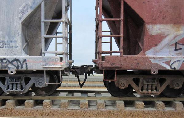
    Hi Al, Those hoppers are old Weaver cars with P48 wheels sets installed in the original trucks.  The magnets will connect on the edge if the polarity is wrong but in a train it's hard to see the difference. I make the airhoses from hollow plastic tubing then glue the tiny magnet to the end in a loop of wire( Ben Brown makes them using cast brass glad hand castings that you might find documented online). The angle cocks are brass tube with handle installed so it can be turned to the open or the closed position, so cars on the end of cuts can look like the air line is closed.The first photo shows an angle cock  under construction and the second is the wire loop for the magnet on the end of the airhose....DaveB

2176

2196

Attachments

Images (2)
  • 2176
  • 2196
Originally Posted by daveb:

 "On the magnets,do you have to have opposite polarity to make them work"


    Hi Al, Those hoppers are old Weaver cars with P48 wheels sets installed in the original trucks.  The magnets will connect on the edge if the polarity is wrong but in a train it's hard to see the difference. I make the airhoses from hollow plastic tubing then glue the tiny magnet to the end in a loop of wire( Ben Brown makes them using cast brass glad hand castings that you might find documented online). The angle cocks are brass tube with handle installed so it can be turned to the open or the closed position, so cars on the end of cuts can look like the air line is closed.The first photo shows an angle cock  under construction and the second is the wire loop for the magnet on the end of the airhose....DaveB

2176

2196

Hi Dave,

This is FANTASTIC!! If it doesn't exist in O Scale it will!! That's my conclusion after reading your post & looking at your pic's. So that's how the polarity problem is solved on the Magnelocks's. I wondered about that often times. I bought a sample of gladhands & anglecocks from,I believe,Precision Scale with plastic tube. I also have some brass flexible tubing from years past,I forgot I had.

How long do you make your airlines so they stay coupled in trains?

What type cement do you use when fastening the hose to the angle cock&gladhand?

How do you fasten them to the car body? Do you have to keep them away from as well as underneath the coupler box a certain distance to prevent coupler swing from hitting them,similar to the Magnelock installation procedure?

I use the Protocraft new couplers,as I want as much Prototype action as possible;i.e. coupling/uncoupling with cut levers,connecting airlines,manually turning switches &derails by groundthrows,etc. (I'm trying to work in talking to the engineer by radio,but haven't mastered that yet as I'm engineer,conductor & brakeman & if the wife hears me talking all the time she'll have me committed). 

Thanks again Dave,

Al Hummel

Something from left field . . . you need DCC for this . . .  remotely operated couplers using muscle wire?


They pull the coupler open as far as you want, and will operate on most curves.


My only working examples are in HO as I've only recently started in O and haven't built any rolling stock as yet, but here's a prototype O scale I made up on a piece of board.


https://www.youtube.com/watch?v=q29cdtFGdUo


Cheers

"How long do you make your airlines so they stay coupled in trains?

What type cement do you use when fastening the hose to the angle cock&gladhand?

How do you fasten them to the car body? Do you have to keep them away from as well as underneath the coupler box a certain distance to prevent coupler swing from hitting them,similar to the Magnelock installation procedure?"


   Hi Al, I'll try to answer your questions. I've added 4 more photos that might help. I make the airhoses length and anglecock placement mostly by eye depending on the car, aiming to have the magnet on end of hose fall under the coupler at a height that will clear the rails when coupled and with enough airhose slack that they won't separate on the curves. Trial and error found the spot then I just copied it for the other cars. I glue the magnets and wire into the hose with ca. glue. The hose is some very flexible hollow stuff I had in my modeling supplies so I don't know where to get it. Ben told me he gets his from a fishing shop IIRC as it's used for fly tying. I've never seen the Magnelock couplers so can't compare their use to mine. I place the anglecock just beside the Kadee coupler box on an angle so the hose points to the centerline below the coupler.I don't worry about the side swing of the coupler hitting the angle cock as I've found they don't need to go all the way to their side stop in operation on my 42/46 inch radius main and passing track curves. Since I make my own anglecocks I just build a long tail of brass trainline into them then attach it to the bottom of the car with whatever method the car underframe requires. These hoppers have a plastic bottom so I just bend a 90 degree turn at the end then heat the brass and push it in flush, then add a wire U near the car end to support it. The first photo shows the airhose connected by their edge, it's not too obvious in this far view but in photo 2 it can be seen. Photo 3 is the view from the end showing the anglecock and hose pointing toward the centerline.Photo 4 is the car bottom showing the brass air line mounted to the bottom of the hopper.....DaveB

air4

air5

air2

air3

Attachments

Images (4)
  • air4
  • air5
  • air2
  • air3
Originally Posted by daveb:

"How long do you make your airlines so they stay coupled in trains?

What type cement do you use when fastening the hose to the angle cock&gladhand?

How do you fasten them to the car body? Do you have to keep them away from as well as underneath the coupler box a certain distance to prevent coupler swing from hitting them,similar to the Magnelock installation procedure?"


   Hi Al, I'll try to answer your questions. I've added 4 more photos that might help. I make the airhoses length and anglecock placement mostly by eye depending on the car, aiming to have the magnet on end of hose fall under the coupler at a height that will clear the rails when coupled and with enough airhose slack that they won't separate on the curves. Trial and error found the spot then I just copied it for the other cars. I glue the magnets and wire into the hose with ca. glue. The hose is some very flexible hollow stuff I had in my modeling supplies so I don't know where to get it. Ben told me he gets his from a fishing shop IIRC as it's used for fly tying. I've never seen the Magnelock couplers so can't compare their use to mine. I place the anglecock just beside the Kadee coupler box on an angle so the hose points to the centerline below the coupler.I don't worry about the side swing of the coupler hitting the angle cock as I've found they don't need to go all the way to their side stop in operation on my 42/46 inch radius main and passing track curves. Since I make my own anglecocks I just build a long tail of brass trainline into them then attach it to the bottom of the car with whatever method the car underframe requires. These hoppers have a plastic bottom so I just bend a 90 degree turn at the end then heat the brass and push it in flush, then add a wire U near the car end to support it. The first photo shows the airhose connected by their edge, it's not too obvious in this far view but in photo 2 it can be seen. Photo 3 is the view from the end showing the anglecock and hose pointing toward the centerline.Photo 4 is the car bottom showing the brass air line mounted to the bottom of the hopper.....DaveB

air4

air5

air2

air3

 Thank you Dave,the information & photos is VERY HELPFUL. Will file this in my railroad folders so I don't lose it.

Great work!

Thanks again.

Al Hummel

Originally Posted by jgtrh62:
Originally Posted by Alan Hummel:

I plan on using 48"&50" curve radii for my double mainline curves. How much straight track should I allow when coming off these curves with a C-40CW diesel,before I cut in my yard switch,which will be a lefthand switch?


Al Hummel

Al another option to consider is installing a curved turnout in that location. I built the following O scale, 60"/48" curved turnout for a friend's layout several years ago. I tested it with Atlas four and six axle locos for several weeks without issue before shipping it to him and he is still pleased with it's operation to date. I did not test any long cars through it though like the 89' flat.
John


60-48CurvedTurnout

John,

Thanks so much for the advise & switch picture which is a WORK OF ART!!

Wish I had the talent & patience,plus knowledge, to make such Craftsman Works.

Thanks again.

Al Hummel

Just dropping this in again; an obvious review for most of you but some that read this thread not in the know may want to include this in the reading. 1:1 -reality a 16 degree minimum curve on Y's for the Union Pacific in o scale this equivalent is a 90" radius

A few other ratios... Just for example.

O-108 Diameter
54" radius

O-72 Diameter (full circumference)
36" radius in 2 rail from center point to edge

O-120 minimum to run my new Key Model Import's FT's are a 60" radius

My absolute minimum is 72" never below.
Fabulous stuff!


Originally Posted by jgtrh62:


I'd guess 48"R requires approximately 5" minimum double track centerline spacing. The inside track in the image below is 80"R with 4" centerline spacing between the outside track and it is close clearance on long cars. The end of the car shown in the lower left corner of the image is a 89' flat and illustrates the overhang on 80"R.

John


80

"Replace those bolsters with P-48 bolsters - they still make them, don't they?"


  Hi Bob, I've seen them for Athearn trucks but I don't know if they made any  for Weaver trucks. These trucks are actually decent for width, the problem is they just don't have the inside bearing housing. Here's a prototype car from the end view to compare.Notice that the truck sideframe, the space between sideframe and wheel, and the  wheel width are all about equal. The second photo is a P48 car with about the same proportions of sideframe,gap,and wheel.....DaveB

2217

wheelsgap

Attachments

Images (2)
  • 2217
  • wheelsgap

"What size brass tubing and wire are you using for those?


BTW, the super flexible vinyl tubing is Larva Lace - I got a pack online from a fly fishing shop."


   Hi Gregg, Thanks for putting a name to the fly tying tubing. That's what Ben used when we were discussing these years ago.  Looks like my angle cock tube is 1/32 or 0.31" with a hole for the 0.20"wire handle( I flatten the handle part of the wire a bit before bending it to shape). The handle is a friction fit into the soldered anglecock body so it can turn without popping out. The short piece of tubing that makes the anglecock is soldered to a solid 1/32 brass train line( solder a long piece with one end where you want it then cut it  off at anglecock body size). I just solder it to the side of the train line after hammering a divot in the train line and the solder blob blends it in

   In operation I found it easiest to connect the air hoses and turn the anglecock handles by using a pair of tweezers. Just pushing the air hoses near each other is enough for them to snap together, the tiny magnets are quite strong for their size.

   Although I enjoyed the experiment I decided to use fixed in place air hoses on my S scale cars partly because I couldn't find magnets small enough to look good on them and also because it was a lot of work making and installing the hoses and anglecocks then operating them when running trains. On the S cars I've been adding formed wire air hoses that just simulate being coupled when viewed from a distance. Here's a couple of examples. ...DaveB

sairhoses

sp9607hicube9

Attachments

Images (2)
  • sairhoses
  • sp9607hicube9
Last edited by daveb

This brake hose stuff is really cool, and I would love to add them to my cars. After sifting through all of Dave's posts I think I have all the ingredients to replicate his recipe, but then it dawned on me:


I'm a 3 railer!


I can't do this, or at least not this way.


I've mulled over the whole Kadee debate and have come to the conclusion that due to the size of my fleet and the nature of my layout it would be impractical at best, to convert.


Even if I was to switch to Kadees, I could never clip the glad hands, because I need to retain the ability to uncouple remotely as a part of the operation of my railroad. I'll give it more thought, and maybe even try some "lobster claw" adaptations.

Last edited by Big_Boy_4005

After looking at a couple of cars, it may be possible to do these for 3 rail, though clearly they would not be as accurate.


Because of the coupler actuator tab placement on most modern cars, the pipe would have to be moved to the opposite side. By drilling a hole in the coupler shank, and bending a 90 in the brass rod, it could be made to work. I really want to give this a try.


I'll be very curious to see what happens when they get near an electromagnetic uncoupler.


Sorry guys, I'm not trying to hijack your forum. I'm just a little excited by this.

the term "selective compression" comes into play a lot in Model RRing.   


For me 90 inch would have only allowed a loop around the basement and trains chasing their tails.  


I like to operate with lots of switching with a purpose ie. put PRR 123456 into the lumber yard siding etc.  


Even 72 inch is pretty big for a home layout.  I stuck with 52 inch minimum on the mainline.   I can run any 40-50 and probably 60 ft cars.   I can run GGD and walthers 80 ft passenger cars.    I can run newer plastic 6 axle diesels but I prefer 4 axle.   I have a pair of Altas Erie builts that don't mind at all.   I also have a fleet of steamers including a Max Grey 2-10-4.   It complains a little but does not derail.   Mikados and decapods have no problems.


My layout is around the walls with a peninsula up the middle.   It runs from staging to staging that is inside the peninsula.  


My suggestion is figure out what kind of track plan you want, and then determine what the largest radius you use to get it.   Obviously for 2 rail O, you can really go much below 48 inch radius and unless you stick with very small equipment.    And if you and a big loop with very broad curves, do it and have fun.

In regards to curves my smallest curve is 36" here are some 52 foot Gondolas being shoved around a 36" curve this happens all the time with no derailments.

I do admit if you have the space larger curves are always better.

My layout is an industrial area so sharp curves I live with but I don't have a problem with em.

Add weight to the cars, metal wheels, Kadees = no problems.

Roo.

DSC08007

Attachments

Images (1)
  • DSC08007

No doubts!   When I said not much under 48, I was thinking steamers and larger diesels and passenger cars.    All can be made to work on that.  


But as you show so well, 36 works with smaller engines and even 50 ft cars. 


I have found that metal wheels are not as important as wheels that turn freely and are smooth so they can slide a little on the curves.   I have both Delrin and metal and both types work well.

Add Reply

Post

OGR Publishing, Inc., 1310 Eastside Centre Ct, Suite 6, Mountain Home, AR 72653
800-980-OGRR (6477)
www.ogaugerr.com

×
×
×
×
Link copied to your clipboard.
×
×