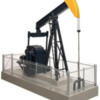
Is it possible to use a DC transformer from an HO train set to run accessories, or would the amperage be too high?


I was wondering if it might be possible to hook my volt meter up an HO DC transformer and crank up the voltage to 10-12v in order to run a few accessories?  Can something like this be done? (i.e. using an HO train transformer as a variable voltage accessory power source)


I know just enough about electricity to be dangerous, and I am aware others use small 'wall-wart' DC supplies/chargers from other applications (e.g. cell phones, outdoor lighting, etc) or they wire up bridge rectifiers, but I have a couple old DC HO transformers so I was just wondering if I can make use of them.


I picked up one of these from Public Delivery Track and from what information I can find it seems it operates on DC.  I would also like to power 2-3 lighted buildings along with this accessory and the DC source I end up using.


atlas o walthers 933-2708


I would also be interested in a suitable stand alone DC accessory transformer or power supply (fixed or variable), if anyone knows of a good option before I tried a homespun solution.

Thanks in advance for any input, information or ideas!

Robert

Attachments

Images (1)
  • atlas o walthers 933-2708
Original Post

Replies sorted oldest to newest

An HO power supply probably has a transformer (all transformers are AC), a rectifier to convert to DC, and a variable resistor to very the voltage. A conventional three rail train transformer has a transformer where the speed control changes taps on the transformer windings.  Modern three rail AC power supplies use electronic components to provide a variable AC voltage supply. A possible problem with using the HO power supply to power accessories is it will be continuously dropping the voltage through a resistor which is going to generate a lot of heat. In time this will result in the resistor failing.  A better solution might be to watch the train shows or auction sites for a small older three rail AC transformer like a Lionel 1033. If you want to run your accessories on DC, put a bridge rectifier on the output. 

Thanks for the replies!  Maybe I should have cited the HO transformer I was considering using...it's an inexpensive old Bachmann 6607


bachmann-hobby-transformer-model-6607


If I'm reading the specs correctly this has two sets of taps on the side of the transformer.  The "track" taps are DC putting out up to 17v (variable by throttle lever & draw I assume), and the "Accessory" taps are AC putting out up to 20v (I'm assuming that is fixed).  Total output is a max of 7amps...correct?


So a simpler way of asking my question might have been to say, 'has anyone used this type of transformer to power DC accessories, or is it just no advisable?'

(It's not that I "want" to use DC, but from what I've read the oil pump requires it...as of now it will be my only DC accessory)


What are the downsides if it is possible to use this model? (e.g. "heat" as David mentioned...is that mainly a concern as I approach the 7amp limit?)


I understand I can also run lighted buildings on DC, so the thought was if this cheap transformer can be pressed into service as a DC source for this one accessory, then I might as well use it to power a couple lighted buildings while I was at it.  I can't imagine the oil pump motor drawing 7a, but I don't have the full specs on it yet.


Would using something like this be markedly different from using say the MTH Z-DC1 (40-200) "Accessory" Hobby Transformer?


I guess this is really just about trying to make use of something I had on hand (free) .  Sorry for all the questions (again, I know just enough to be dangerous), and thanks again!

Robert


PS Thanks Wild Mary, just saw your post as I was writing another long response (sorry about the length).  I figure I'll fall back to one of those types of supplies if this approach is not advisable.

Attachments

Images (1)
  • bachmann-hobby-transformer-model-6607
Last edited by MakingTheGrade

Just to be clear, I'm not forced to use this HO transformer it's just a thought because what I've read said the Atlas - Walthers Oil pump requires DC (PDT description said it will run on AC or DC, but researching suggests in only runs on DC).


I don't want to run the risk of damage to the accessory trying to go this route...no intention of using the 20vac output for anything.


And if I use it only for the pump, that's fine too, as I can keep my few lighted accessories on the 14vac side of the z-1000 brick I'll be using.  Just looking for a cheap DC source for this one accessory...and this is cheap if it works.

Robert

One option is to set your HO DC output transformer to its highest voltage (e.g., 16V) and use local point-of-use regulator modules to provide exactly the voltage you need for each accessory or group of accessories.  For example, it's likely your pump runs at a different voltage than your lighting.


LM2596 module

The conventional method to provide multiple output voltages for accessories from a single voltage source has been to use resistors or diodes to "drop" the voltage.  While electricity may be "cheap" in the USA, this approach is simply wasteful.  Virtually all modern power supplies use so-called switching supplies (like the module shown) to convert voltages.  These have superior conversion efficiency in many cases providing more output current than input current which can take some getting used to!  Say your accessory needs 1/2 Amp at 6V.  That's a power of 3 Watts (Power = Voltage x Current).  If you start with a DC transformer at 16V and drop it to 6V the traditional way using diodes, resistors, or whatever, you still draw 1/2 Amp from the 16V source or 8 Watts and the extra 5 Watts becomes wasted heat.  OTOH, using one of these modules, you might draw about 1/4 Amp or 4 Watts.  


The amazing thing is these modules can be had for just over $1 each with free shipping from Asia if you are willing to use eBay and wait maybe 2 weeks to get one.  Search eBay for "LM2596 module" and you'll get hundreds of choices.  Or search OGR for "LM2596" for other threads discussing these modules.  BTW, LM2596 is just a part number of an IC chip used in many of these modules.


In case it's not obvious, you can also start with a DC wall-wart supply you might have lying around.  And you can "parallel" or hook-up multiple modules to a single DC supply to generate a set of regulated DC voltages.

Attachments

Images (1)
  • LM2596 module
Originally Posted by MakingTheGrade:


 The "track" taps are DC putting out up to 17v (variable by throttle lever & draw I assume), and the "Accessory" taps are AC putting out up to 20v (I'm assuming that is fixed).  Total output is a max of 7amps...correct?


First, I doubt that power pack would come close to that 17 V spec under any load at all.


More importantly, that isn't a 7 amp capacity, but a 7 VoltAmp which is "sort of" equivalent to only 7 watts of power. For comparison, just about the smallest, most basic 3-rail transformer is rated at 40 watts.


I'm not sure what the power requirements are for that oil pump. 7 watts might do it, but I'd check first.


Jim

Many thanks Stan & Jim for the replies.  I'm beginning to understand this puzzle better.  Stan, I like that device if nothing else for it's compact size and aesthetic value over the daisy chained diodes wrapped in electrical tap that I've read about.  Also knowing it would be more efficient and reduce waste/heat seems like a big plus.  I realize from working with DC in automotive wiring that it's main downside is the heat it creates.


My electrical experience has been limited to some work on cars and

construction.  Basically I can figure out how to route and supply, but don't understand near enough on the consumption or usage side of electricity other than the old watts=volts x amps.  Actually that's one of the areas I can see this hobby helping me grasp.


Sidebar:  A quick novice question...when you're turning down the power via a modern transformer model, is it most likely reducing power through resistors or 'switching' through the 'point-of=use' device (LM2596)?


Jim, thanks for the clarification of the 'Volt-amps'.  I had missed that and was not aware of it's "sort of" equivalence, nor the true output capability of the cheap transformer.  Looks like more reading to do about that and the "point of use" piece Stan pictured.  Likely pick one of those up just to experiment.


Honestly the pump would make a fine static display, as most were that dotted the Texas landscape during the oil crisis of the 70's and my youth.  Obviously though I do want to get that "horsehead" (grasshoppers are what we called them as kids), working correctly and efficiently.

Thank you gentlemen

Robert

I don't know a lot about train power but I have 5 of the pumps you have and use a MRC TECH II Railpower 1400. I had it for a couple of HO trains that I have but don't run at this time. I do run the pumps slow but if I turn the trottle the pumps will really go.


I do have the pumps connected to the DC connector not the AC


Brent

Originally Posted by BReece:

I don't know a lot about train power but I have 5 of the pumps you have and use a MRC TECH II Railpower 1400. I had it for a couple of HO trains that I have but don't run at this time. I do run the pumps slow but if I turn the trottle the pumps will really go.


I do have the pumps connected to the DC connector not the AC


Brent

Thanks for the tip Brent!  I came across your thread where you were looking for a motor for one of your five...glad to hear you got them all operating.  These were a familiar sight on all our family road trips as kids.


I also read they tend to be a bit noisy when running, but hopefully it won't be too bad.  I've come to expect some noise with operating accessories, and I like the active layout.  I would like to get it to emulate that slow loping action of the prototype.  I would have gone for a couple if I had more room.

Robert  

I really doubt that you can use a small H.O. transformer or as it is called in H.O. world a power supply. The H.O. power supplies are very low watt and may be over taxed by using it above it's output rating thereby failing quickly or within a couple of weeks use.

The better solution would be to use an older Lionel transformer rated at 40 watts or better from a starter set or something. An older post war single train transformer should work with most Lionel accessories, if it is a newer accessory you must watch for the voltage to match very closely.


Lee Fritz

Lee,

As Robert stated earlier, this particular accessory operates on DC not AC. He is just trying to avoid having to use a rectifier with an AC transformer.


Robert,

Using an HO power pack is an excellent idea. It's just that the one you have on hand is a particularly small, underpowered model. You often see those MRC 1400s that Brent suggested on the used market for less than $20. It is a great little DC source.


Jim

Jim,


From what I know about rectifiers, they are not that expensive to buy.

Also like you mentioned the small H.O. power unit has very little output. I had a Lionel engine a few years back that ran on D.C., I used a small power unit like Robert mentions and the Lionel engine just barely crawled.


I would imagine that the H.O. train clubs have a very large power supply for their layouts and that should have enough power for several accessories.


The advantage to running on D.C. power from what I have heard is that you don't have a buzzing noise from some accessories.

However I am not that into running some accessories on D.C. as it requires more work to set-up.

I am more into the three rail A.C. side of the hobby. But have done a couple of conversions of a Williams engine to a bridge rectifier, because the circuit boards didn't work like I wanted them to.


Lee Fritz

I forget who actually made those flip handle, turn one way for forward, the other for reverse power packs, but they made them for Bachmann, Life-Like, Lionel, and I believe Model Power. The output voltages on the case are "open circuit, no load" voltages measured with a high input impedance meter. The guts are the same in all of them, just different cases. You can usually pick them up for $5 or so.


That said, I've used them for years for HO, O, and G DC powered accessories, with the caveat of 1 accessory per power pack for O and G. Besides, putting them on seperate power packs lets me set the voltage for the speed I want on each accessory.


It's all about power output.


In the 3-rail AC world, we think of a 40 watt transformer as small. Average is about the 90 watt output of a postwar 1033.


But, in the HO world, 40 watts would be huge. Only the most powerful packs exceed about 20 watts.


For an accessory that requires DC, such as the one the original poster was inquiring about, one advantage of a good HO power pack over rectified postwar (and some modern) transformers is the starting voltage. There is practically no control from the 0 mark to about 5 volts. A good DC pack will provide much more control in this low voltage range.


As far as running older Lionel accesssories on DC, remember that any whose motion is based on a vibrator "motor" mechanism will work only on AC.


Jim


Originally Posted by Jim Policastro:

Lee,

As Robert stated earlier, this particular accessory operates on DC not AC. He is just trying to avoid having to use a rectifier with an AC transformer.


Robert,

Using an HO power pack is an excellent idea. It's just that the one you have on hand is a particularly small, underpowered model. You often see those MRC 1400s that Brent suggested on the used market for less than $20. It is a great little DC source.


Jim


Thanks again Jim!  That is precisely what I was/am hoping to do...use the small HO transformer to run only this one DC accessory.  I have a relatively small layout (4'x8') and don't envision adding any additional DC accessories (famous last words ... because I do like operating accessories), but I'll still keep an eye out for the MRC model in case I can pick one up cheap.


Originally Posted by Len2:

I forget who actually made those flip handle, turn one way for forward, the other for reverse power packs, but they made them for Bachmann, Life-Like, Lionel, and I believe Model Power. The output voltages on the case are "open circuit, no load" voltages measured with a high input impedance meter. The guts are the same in all of them, just different cases. You can usually pick them up for $5 or so.


That said, I've used them for years for HO, O, and G DC powered accessories, with the caveat of 1 accessory per power pack for O and G. Besides, putting them on seperate power packs lets me set the voltage for the speed I want on each accessory.


Thank you Len!  If this little HO transformer would be capable of running just this one oil pump rig without burning up the transformer or the rig and I could vary the voltage to get the slow movement I want, then that would be fine with me.  The ability to vary the voltage/speed using a DC transformer handle is what originally got me thinking of this approach.  Although I'm still not quite sure how a transformer is doing this when you move the throttle (I'm assuming varied resistance?) and what that means for long-term operation.


I'm waiting on the oil pump to arrive from Public Delivery Track, and in the meantime cannot find the user manual or instructions online anywhere to verify the electrical specifications (recommended current, amp draw, etc...the PDT listing stated 8-12v but that seems high compared to what others have stated).


I did come across another of BReece's threads where he attempted to use AC and only got a "hum", so I'm pretty sure the "AC or DC" comment in PDT's listing is just a typo.


I'd like to still test run the pump on the HO transformer using my volt meter, but again I'll likely be picking up a couple of the 'point-of-use' modules Stan posted, as doing some research I also found where you can also get them with AC or DC inputs as well (LM317).

Seems like they would be handy devices to have on hand.

Robert


Hey Stan, that looks just like an old Tyco box I have/had...I'll have to dig up the rest of my HO remnants.  I have to admit it, but for someone in their mid forties who is quite comfortable with computers...I've never owned a laptop, and still haven't found the need for a laptop or even a smartphone  I'm sure there's a trendy name for it, but I'm a low tech guy when it comes to the 'constant communication' society  That's why the surplus chargers or wall-warts are not a ready solution in my case.


Yes my vintage analog meter does have DC voltage settings, and I plan on running that very test, and letting you guys know what I find.

Thanks again,

Robert

Some things about DC power:


1.  Don't mix it with track AC via common returns, et. al.  It will cause horns or bells to go off all the time.

2.  It will not make things which have a vibrating motor work.  They work because of the AC current.

3.  DC does have a voltage drop,

4.  Lights MIGHT last a shorter time on DC.  They stay on all the time.  With AC, there is a voltage cycle with the Alternating current, and for a moment they are actually OFF.  But at 60 cycles/sec., your eyes cannot see it.

5.  An electrics parts store of a ham radio store might have low cost DC power supplies for sale.

I've simple created two DC circuits from my Z4000 from each of the accessory outputs.  I have the AC output circuits, but run DC currents as well with a full wave bridge rectifier (really cheap at Radio Shack).  I use  rectifiers that are totally over rated so I never worry about overloading it.  They loop around my layout, and I tap into them where needed.

Alan

The HO DCC guys use 15 volt 5 amp (75 watt) AC power supplies to run their layouts. You can get them from NCE, MRC and other DCC manufactures. I use a a couple of older MRCs with a 15 and 18 volt outputs. I don't think they are any longer available. You can also use the wall packs that come with many electronic devices, just check if the output is DC or AC and the current rating.

Thanks Dominic, Jon, Alan and Richard for your tips and suggestions.


Just getting back to this thread after returning from vacation, and happy to see my Walthers Oil Pump arrived while I was gone.


However, there is an interesting development upon opening the pump package...


There was this note about using AC along with the instructions (that call for DC)...


oil pump 030


This was the best picture I could take of the "diode"...


oil pump 020


It's mounted on the positive wire feeding the "DC" motor, so my question is:

Can a simple diode be used in this way (to run a DC motor on AC voltage)?


I was under the impression that a bridge rectifier was needed, but don't know that much about electronics, so any help would be greatly appreciated...I just don't want to attempt to run this setup and risk damage to the model.  I don't know if this was a running change in production of the Walthers Oil Pump or what

Thanks,

Robert


EDIT: Re-reading Stan's and others' posts, I think I understand diodes can be used to drop voltage, but for running (converting) AC to DC...that's where I'm puzzled.

Attachments

Images (2)
  • oil pump 030
  • oil pump 020
Last edited by MakingTheGrade
Originally Posted by MakingTheGrade:

Thanks Dominic, Jon, Alan and Richard for your tips and suggestions.


Just getting back to this thread after returning from vacation, and happy to see my Walthers Oil Pump arrived while I was gone.


However, there is an interesting development upon opening the pump package...


There was this note about using AC along with the instructions (that call for DC)...


oil pump 030


This was the best picture I could take of the "diode"...


oil pump 020


It's mounted on the positive wire feeding the "DC" motor, so my question is:

Can a simple diode be used in this way (to run a DC motor on AC voltage)?


I was under the impression that a bridge rectifier was needed, but don't know that much about electronics, so any help would be greatly appreciated...I just don't want to attempt to run this setup and risk damage to the model.  I don't know if this was a running change in production of the Walthers Oil Pump or what

Thanks,

Robert


EDIT: Re-reading Stan's and others' posts, I think I understand diodes can be used to drop voltage, but for running (converting) AC to DC...that's where I'm puzzled.

Adding a diode to an AC supply will provide half wave pulsed DC voltage. The RMS will be equivalent to about half the AC voltage in. (slightly less than half due to the forward drop of the diode). So 18 VAC would supply about 9 VDC (RMS) to the accessory. It may run fine this way depending on how it is made. Lionel vibrator accessories actually work better this way than on AC due to the unbalanced wave form. I am not familiar with the oil pump so I can not say for sure,but I think it would work. If it needs a filtered supply it can be made from and AC transformer with a bridge rectifier and a capacitor,regulated if needed with a 7812 regulator or voltage reduced after the bridge with a diode string. No real need for the HO transformer although it would work.


Dropping voltage with diodes is explained here


www.jcstudiosinc.com/BlogShowThread?id=413


Here are paired diodes dropping voltage for AC. For DC only a string in one direction is needed.


voltagedropper


Dale H

Attachments

Images (1)
  • voltagedropper
Last edited by Dale H

Many thanks for the information Dale!  I'm learning more and more about electronics via this hobby


Could you or someone here please explain in layman terms the difference between this "half wave pulsed DC voltage" versus the 'full wave' rectification provided by a bridge rectifier?


What would be the pros or cons of using one versus the other in the example of this DC powered oil pump accessory, is it the "filtering" or is there a notable difference in the operation of the motor?


I'm surprised the additional note enclosed with the oil pump does not mention halving of voltage..."12 volts max. 8 volts is best" (from the note)...that would be 6 volts and 4 volts respectively.

Thanks again,

Robert

Originally Posted by MakingTheGrade:

Many thanks for the information Dale!  I'm learning more and more about electronics via this hobby


Could you or someone here please explain in layman terms the difference between this "half wave pulsed DC voltage" versus the 'full wave' rectification provided by a bridge rectifier?


What would be the pros or cons of using one versus the other in the example of this DC powered oil pump accessory, is it the "filtering" or is there a notable difference in the operation of the motor?


I'm surprised the additional note enclosed with the oil pump does not mention halving of voltage..."12 volts max. 8 volts is best" (from the note)...that would be 6 volts and 4 volts respectively.

Thanks again,

Robert

Hello Robert


During the infancy of electrification of America there was competing ways to generate it. Thomas Edison wanted DC and Tesla developed and wanted AC.  Tesla's AC system won out and that is the standard today in America. AC is generated in pulsed current. On a scope it looks like this


alternating-current1


For convention in America it was decided that the generator turn at 60 RPS. So 60 of these complete cycles happen each second. Power is transmitted at high voltage,in 3 phases then split,then stepped down with transformers. 220 volts AC come into your house and is in your service panel then it is split again into 110 volts for your common wall socket.( A heavy appliance such as an electric stove may still use 220).


Now if you plug in a PW type transformer into thew wall,the voltage is reduced again down to 18 volts. The above sine wave then pulses peaking from about + 25 volts to -25  volts,60 times per second. Notice sometimes it is zero. The average voltage is 18 called RMS (root means square). RMS time 1.41 is the peak voltage.


If a diode is added in series to a load half of the sine wave is blocked and the other half is conducted with a .6 volt drop. It would look like this,with the diode reversed it would block the top half and conduct the bottom half.


AC-current-rectified-to-a-pulsating-DC-current-after-passing-through-a-positive-biased-diode.-This-is-called-half-wave-rectification


Since half the wave is blocked you get half of the effective power. So 18 VAC becomes 9 volts DC.  A motor,light bulb etc would run OK this way and if we wanted 9VDC this would work.   The asymmetric wave would also vibrate those old Lionel types better such as the radar tower.


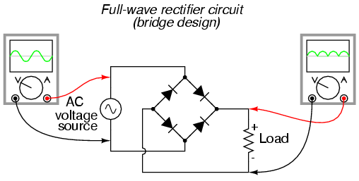
Now if a bridge rectifier is used ( 4 diodes configured a certain way),the sine wave would look like this


fullwave


Neither half of the wave is blocked,so 18 volts AC in would be 18 volts DC out. There would be a small voltage drop from the bridge,about .6 volts. This would be too much for your accessory but a string of diodes in series with the load would drop voltage further if needed.


Adding a capacitor would straighten out the pulsed current and if it were sufficiently large for the load it would approach a straight line instead of pulsing


sRXde


The voltage would also be charged to peak,so 18VAC in would become 25 volts DC out (18 times 1.41,the square root of 2)


Electronic devices,computers.radios,etc like smooth DC current,called filtered DC. This type current is also made from a battery.  A voltage regulator installed would provide various voltage needed. 7805,5 volts,7812, 12 volts whatever the device needs. Your car has one of these to run instruments and lights. The alternator generates AC,it is rectified full wave then goes through a regulator I think.


Filtered DC can be made from either the bridge rectifier (Full wave) or the single diode (half wave). The bridge rectifier is more efficient  and less capacitance is needed for the same results.


03263


Here is a good Utube video explaining


www.youtube.com/watch?v=cyhzpFqXwdA


Dale H

Attachments

Images (5)
  • alternating-current1
  • AC-current-rectified-to-a-pulsating-DC-current-after-passing-through-a-positive-biased-diode.-This-is-called-half-wave-rectification
  • fullwave
  • sRXde
  • 03263
Last edited by Dale H

Hi Dale,

Thank you very much for taking the time to post those graphs and provide an explanation of Diodes versus Bridge Rectifiers in the conversion of AC to DC.  This is great info and very helpful as I try to further my understanding through this hobby (the youtube video was also very helpful).


Since half the wave is blocked you get half of the effective power. So 18 VAC becomes 9 volts DC.  A motor,light bulb etc would run OK this way and if we wanted 9VDC this would work.   The asymmetric wave would also vibrate those old Lionel types better such as the radar tower.

So if I'm following your comments and the information correctly...

If I leave that diode in place and hook the motor up to the 14VAC accessory output of a Z1000 brick, then the motor should see half wave rectified ~7VDC (the literature recommends it runs best at 8VDC).


One additional question that comes to mind is...

Will having a diode on one leg of this accessory affect another AC accessory that might share the +/- connections supply source terminals on the Z1000 brick?  (sharing connections 'upstream' from the diode as it were)


My plan is to test the pump under each method just to see the difference in how it operates if any...1)without the diode and the pump connected directly to a small HO DC power supply, and then 2)with the diode inline and with the pump connected to the 14VAC accessory terminals of a z1000 brick


I realize I should probably take the time to read a full book on the basics of electricity, but I much prefer to learn by application and experimentation...as long as I can refrain from damaging anything  

Thanks again,

Robert


Originally Posted by MakingTheGrade:

Hi Dale,

Thank you very much for taking the time to post those graphs and provide an explanation of Diodes versus Bridge Rectifiers in the conversion of AC to DC.  This is great info and very helpful as I try to further my understanding through this hobby (the youtube video was also very helpful).


Since half the wave is blocked you get half of the effective power. So 18 VAC becomes 9 volts DC.  A motor,light bulb etc would run OK this way and if we wanted 9VDC this would work.   The asymmetric wave would also vibrate those old Lionel types better such as the radar tower.

So if I'm following your comments and the information correctly...

If I leave that diode in place and hook the motor up to the 14VAC accessory output of a Z1000 brick, then the motor should see half wave rectified ~7VDC (the literature recommends it runs best at 8VDC).


One additional question that comes to mind is...

Will having a diode on one leg of this accessory affect another AC accessory that might share the +/- connections supply source terminals on the Z1000 brick?  (sharing connections 'upstream' from the diode as it were)


My plan is to test the pump under each method just to see the difference in how it operates if any...1)without the diode and the pump connected directly to a small HO DC power supply, and then 2)with the diode inline and with the pump connected to the 14VAC accessory terminals of a z1000 brick


I realize I should probably take the time to read a full book on the basics of electricity, but I much prefer to learn by application and experimentation...as long as I can refrain from damaging anything  

Thanks again,

Robert


Robert


As long as the diode is in series to just that accessory none of the others should be affected.


14VAC would be the equivalent of a little under 7 VDC. Try the pump,see if it works that way. If not you could try adding a very small capacitor such as a 1 uf up to a 10 uf NP one across the accessory terminals. See the linked Youtube video for an explanation.


It could be argued that incandescent bulb filaments would last longer on AC at a given voltage. DC current has less resistance to flow than AC impedance,but I will not argue the point.


Dale H

First my background. I graduated from DeVRY Technical Institute in the field of electronic communication. I hold a FCC First class radio-telephone license which is needed to work on any radio or television transmitter. I also worked for 25 yrs. for the Bell system, 15 1/2 yrs for Ohio Bell ,9 1/2 yrs. for AT&T. Part of this time I was the tech. at the repeater sta. in Springfield, Ohio. this repeater station was on the First Transcontinental Cable Network. It was placed in service in 1927 & removed from service in 1976. I worked in the sta. from 1970 until it was removed from service in 1976. Some of the circuits that came through this repeater station were all of audio for radio  networks & all of the audio for tv. networks. The repeater sta. was an amplifying point It was filled with 44-A-1, 22-A-1, & 22-A-2 repeater sets (amplifiers) The  filament   in the vacuum tubes in the repeaters were powered by  DC . Some of the vacuum tubes had been placed in service in the mid 1930's & were still working in 1976. All this equipment was made by Western Electric. So DC is the way to go for lighting on your layout. I use it for lighting on my layout .I have not had replace any light bulbs in 10 yrs.

I use a similar DC power supply on my modified gantry crane.
I use it to run a Dc can similar to the ones already on the crane to move the crane forward and backwards on a crane track via a pulley system.

Works fine for similar applications and running LED lighting.
The key is to figure out the load and for continuous duty make sure that the power supply is rated for that current plus at least 20%

FMH

Although not applicable for the motorized accessories discussed here, I have successfully used a 12 VDC "wall wart" transformer to operate the 12 volt Tortoise motors that power my Ross and Curtis switches.


On my current small layout rarely are more than two switches thrown at the same time. The backup is a large recycled MRC Power Pak that I originally used to power 28 Tortoise motors on a now dismantled O Gauge layout. In that case a number of ladder track switches could be thrown simeltaneously.


Post

OGR Publishing, Inc., 1310 Eastside Centre Ct, Suite 6, Mountain Home, AR 72653
800-980-OGRR (6477)
www.ogaugerr.com

×
×
×
×
Link copied to your clipboard.
×
×