In response to a different thread that I started, another forum member (John Galt Line) offered to help me with a project to control Atlas switches and led indicator lights with an Arduino.

 I have written the code for the Arduino, and now I am deciding how to send a signal from an insulated rail to the input pin of a shift register. I am thinking about using an AC input optocoupler that would be activated by either the insulated rail section or a momentary push button on my control panel.

Here is the plan (a crude drawing is also attached below):

  • Connect 1 input pin of optocoupler to 10v AC post of transformer through 330 ohm resistor
  • Connect 2nd input pin to insulated rail section and momentary switch
  • Connect emitter pin of optocoupler to DC ground
  • Connect collector pin to shift register input pin
  • Pull shift register pin HIGH by connecting to 5v DC through 10k resistor
  • Shift register pin will change to LOW when insulated rail or switch is activated


I would welcome any suggestions. Am I on the right track or is there a better way to do this?

Attachments

Original Post

Replies sorted oldest to newest

For whatever reason I can't read your crude docx but in any event some comments:

- You only need to drive an optocoupler with, say, a few mA.  A 10V AC source thru a 330 ohm resistor into a ~1V optocoupler is overdriving the optocoupler if the output is driving a low-current digital input to a shift register.  That's a peak current of ((10V x 1.4) - 1V) / 330 ohms = 40 mA into the optocoupler.   A 1k resistor is more than enough.

- If you're driving any "modern" digital input, you don't need to pull it up with 10k.  You can lower current by 10x with a 100k pullup resistor.  10k pullups are a holdover from the last century with bi-polar (TTL) inputs.  Anything digital today is CMOS which has negligible input currents.

- By using 100k (instead of 10k) you can use, say, a 0.1uF capacitor across the input to smooth out the AC ripple.  Yes you can "debounce" or smooth the ripple in software but that's just silly if a 1 cent capacitor can do the same.

- Then, if you put that filtering cap on the input you can use a single-ended optocoupler rather than an AC input optocoupler.  AC input optocoupler can run you 2-3 times the cost and are fewer choices.  Of course if you already have a bag of AC optocouplers then never mind.  By using a capacitor as described above it will still filter the half-wave output from a single-ended optocoupler so your digital input still sees a steady DC voltage (no software debouncing).  Then just put in a 5 cent diode on your 10V AC source to feed all your single-ended optocouplers with half-wave DC (so as not the apply reverse voltage to the optocoupler).


Here is a circuit I use to generate a clean logic signal to a shift register from an insulated rail:

sensor

Note that I use an RC debounce and feed the signal into a Schmitt trigger buffer to generate a clean transition from a noisy signal. This takes care of the AC ripple as well as intermittent contact between the wheels and the third rail.

Debouncing and filtering could be performed in software, but I originally built the circuit for a microcontroller that had very little memory or processing power, so software debouncing wasn't an option.

Attachments

Images (1)
  • sensor
Last edited by Professor Chaos

Stan,

Thanks for the advice. I wasn't sure how much current the optocoupler needed. I will change the resistor on the input to 1k and the pull up to 100k. I already have some AC optocouplers, so I think I will stick with them. 

Professor Chaos,

Your circuit diagram was very helpful. Do you have any recommendations for a specific part that I could use for the Schmitt trigger. I would prefer a chip with 6 or 8 channels because I have several switches to control. I am a novice, and I'm having difficulty deciphering all the specifications and deciding which part to buy.


John

Finally have a moment to get back here, sorry for the delay.

Using the optocoupler from track power as described above should work out just fine, but I'm a little concerned if it would work properly under varying track voltages.  Under command operation it wouldn't be a problem, but in any case I prefer a different method.  

I would use a separate DC power source with its ground connected to the outside rail bus of the layout.  When the insulated rail is bridged by passing wheels it would complete the circuit to allow that DC source to power the optocoupler.  This would insure that the LED in the opto is fully turned on and not over driven.  

Something else to note on the output stage is that you will need to use transistors or some other driver between the shift registers and relay boards or LEDs.  The 74HC595 can supply 25mA on one output, but can only supply 70mA total, so if more than a couple outputs are turned on it will over drive the chip if outputs are directly driving relays/LEDs.  

I looked over the sketch posted in the other thread, and if it does the job that's needed it's great.  It is massively less complex than the sketch I have going.  I have some concerns about what is going on there, but will need to test it out with hardware to see  exactly how it is working and if my concerns have any merit.  

The sketch I have going reads all inputs, stores their values, then decides what to do with them before sending out all data to the outputs.  All this makes for a pretty inefficient program, so I'm hoping that what you have will actually get the job done.  

It isn't really a problem yet, but also just wanted to make sure you're aware that the EEProm in the Arduino has a limited life.  Under normal conditions as used in your sketch it should last many, many, years, but under testing conditions it's life can be quickly expended, so just be aware of that and make sure your code doesn't write to the EEProm any more than it needs to.  

Anyway, that's about all for right now.  

JGL

JGL,

I hope you don't mind that I am working on this at the same time as you. I initially wanted to learn enough so that I would understand what you are doing, but I got interested in the Arduino and decided to go ahead and take a stab at the program. I'm also becoming comfortable with the components so you won't have to hold my hand through the wiring process.

I have an unused fixed 10V post on my transformer that I plan to connect to the optocoupler.  Do you think that would be okay? It would be easy to switch to another source at this point. 

Here is a link to the relay board that I purchased for testing. It uses a separate 12v power supply to run the relays. The relays are activated by a LOW signal from the shift register, and I read somewhere that this only uses 3 mA of current.  I can also power the indicator lights through a relay to reduce current flow through the shift register. Let me know if you think I need the transistors with this setup. I am going to need some help on the transistor circuit if you think it is necessary.

I was aware of the memory issue with the Arduino. I'm trying to be careful while testing, but I will probably shift the storage to a different memory location once I've finished all the testing. The code is written so that it only writes to memory when a switch is thrown and only reads once in the startup.

Let me know if you need an explanation of anything in my sketch. Here is a basic outline of the flow of the sketch:

1. Read all inputs from shift registers (assumes 4 switches to each register, each switch on 2 consecutive pins)

2. Check to see if a timer is running for each input (a timer running indicates that power has already been turned on to the switch coil and led)

3. If the timer has been running less than 1 second then maintain power to the switch coil

4. If the timer is between 1 and 3 seconds then remove power from switch coil (this keeps down chatter from the insulated rail)

5 After 3 seconds reset the timer to 0 unless the input indicates that the insulated rail section is still occupied or a button is being held down. (This way the sketch will keep checking every loop and reset the timer to 0 once it no longer senses a signal from the insulated rail.)

6. If no timer is running then if a signal is present at an input, turn on power to switch coil and led. Also turn off power to opposite led and start timer.

7. Send all outputs to shift registers. ( 2 output registers for each input register. 1 for switch coils and 1 for led's)

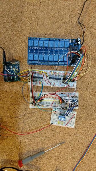
I just want to update everyone on my progress. Today I had a successful test on my layout controlling a total of 8 inputs and 16 outputs (8 switch coils and 8 indicator lights). Here is a picture of what I have now:

IMG_20170214_203507760

It's a jumble of wires now, but I found some solderable breadboards that have the same layout as the larger solderless ones I used. I will be able to fit enough components to control 8 switches (16 inputs/32 outputs) on 3 boards. I should also be able to clean up some of the wiring and add screw terminals for connections to the layout.

Thanks to everyone for your help. You gave me a lot of great ideas and kept me from making several mistakes.

Attachments

Images (1)
  • Arduino project

RTR12,

For the first part of my project I used the circuit proposed by Professor Chaos. 

schmittTrigger

I only made a few small changes. I am using 10V AC Hot as an input so I changed the resistor to 1k from 1.5k. The arrow going to AC common leads to an insulated rail section and a momentary push button on the control panel. The AC is connected to this optoisolator , and this is the Schmitt trigger that I used. It is slightly different from the one drawn above because it inverts the output signal. (When the button is pressed or the insulated rail connected, the signal going into the Schmitt trigger is LOW and the signal coming out is HIGH). I had to use this part because I could not find a non-inverting one with through hole mounting. The Schmitt trigger is connected directly to an input pin of a 74HC165 parallel in shift register.  My Arduino sketch requires that the 2 inputs (straight and diverging route) on each switch are connected to adjacent pins on the shift register. I plan to chain 6 shift registers together on one board so I can handle a total of 24 switches. The basic purpose of the Arduino sketch is to make sure that power is only applied to switch coils for a short period of time even if a train is parked on an insulated rail. The sketch also maintains power to the appropriate indicator light and will remember the switch positions even after power is turned off.

The shift registers are connected to the Arduino by 4 wires. The connections are described in the comments at the top of my Arduino sketch. The sketch outputs data to twice as many 74HC595 parallel out shift registers. These are connected to the Arduino by 3 wires. The data is output in the following order: input from the first register (closest to Arduino in chain) is sent to the last (farthest in chain) output shift register. This register controls the relays for the switch coils. The next to last output shift register controls the relays for the led's. The data output continues in this alternating pattern of coil / led control.

I am using this relay module to receive the output from the shift registers. It does not come with instructions, but the only required connections are the 12v dc power source (2.1mm plug), a 5v connection from the Arduino, and one wire from each shift register pin to a numbered pin on the relay board. John Galt Line suggested using transistors to power the indicator lights instead of the relays. I ordered a few transistors, and I am going to experiment with them. At first glance it seems like they would be less expensive and take up less room.

I am planning to build permanent boards to control 8 switches and try them out on my layout for a few weeks before continuing. Let me know if you have any questions about the details.

John


Wow, that was a great description of EVERYTHING, Thank You! I need to do a little studying now and look at the data sheets for the devices. I am getting a little better at figuring those out. Also, I think I may have a couple of the parts already and I might try to breadboard this myself. You certainly picked up the Arduino programming very quickly, as well as ALL of the other stuff too. I would agree that the transistors that JGL suggested would make for a smaller package when finished.

The only thing that didn't come through was the picture, it says 'Image Not Found'. I am guessing that it was the same picture that Prof Chaos posted above? If so I will just use his schematic.

Thanks again for taking the time to explain all this and with good parts links too. I am guessing there will be others interested in this as well. Great project and you got is all figured out pretty quickly too. 

Please keep posting your progress and how your testing goes.

Thanks again for the update on the project with all the details!

RTR12,

Yes. The missing image is the same as the professor's diagram. One thing that helped me was to put each component on the breadboard individually to make sure that I knew how it worked. I then started combining components and testing the results. The optocouplers and Schmitt triggers both have pretty simple wiring schemes, so they were pretty easy. The shift registers were more complicated, and I was glad I spent some time experimenting with them.

First off, great work, John.  I'm glad you are getting things to work and you're not having much trouble with the components or Arduino coding.  

I'm still plugging away at this project as time allows, hoping to make a solution that is useable by anyone that wants to throw the parts together.  

Up until now my progress has been pretty much in parallel with the prototype JohnF has posted above.  I use some slightly different components but the functionality is about the same.  As of now, however I'm changing directions as a "less-complex" idea has come to me.  Before getting into that, I figured I'd share some of the layout and such I had completed.  

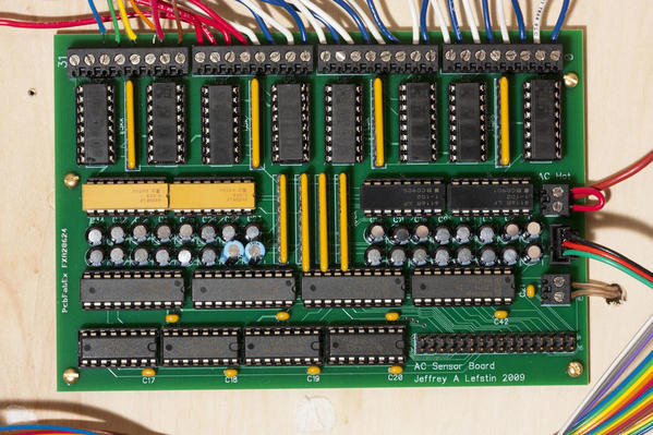
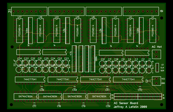
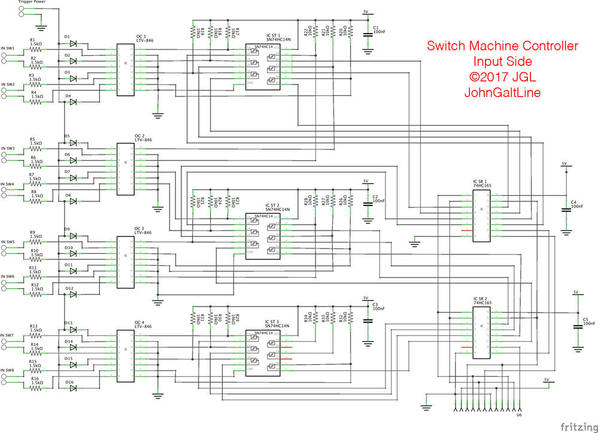
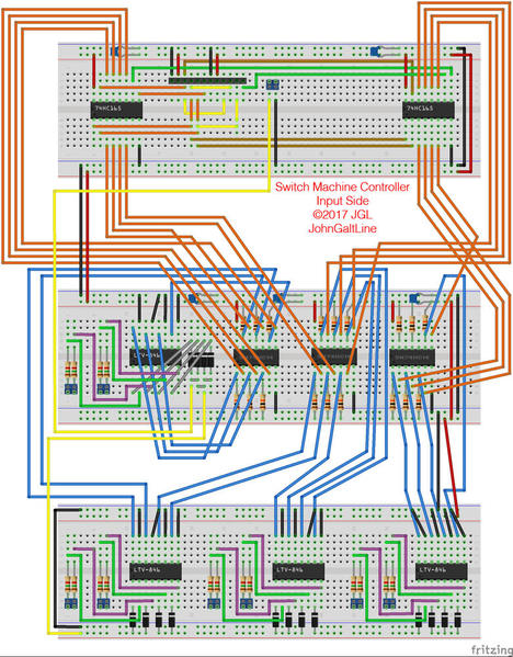
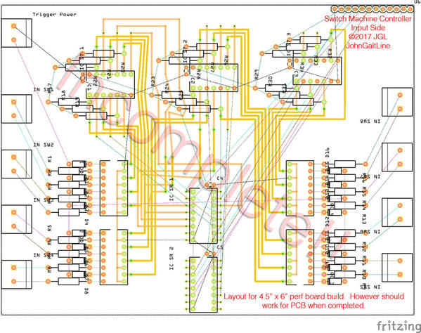
SMC01SMSMC01BBSMC01PCB

This was the input side of the project, this board capable of sensing inputs for 8 switches.  It also allows for daisy-chaining of several more identical boards to control more switches.  The PCB layout is unfinished as I came up with a new idea to try out while working on it.  It's also not a real PCB design, but instead intended to be built on perforated proto-board in a common 4.5" x 6" size.  

While working on this project some of my main goals were to keep cost as low as possible, and to make it build-able by folks with little experience in electronics.  I used through-hole components for ease of assembly, and used inexpensive, common, components wherever possible.  All told this input module isn't the worst thing ever, but I think I can do better.  The cost is somewhere right around $12 in parts for this half of the circuit, which isn't all that bad, but it is way more complex for that cost than I'd like.  

On to the controller version 2.0:

I'm going to try out replacing the Schmitt triggers and Parallel to Serial shift registers with a micro-controller.  For about the same part cost (in the sort of low quantities we're using here) an Arduino Pro mini can replace 7 IC's on the board.  All of the information I've found so far seems to suggest it's going to work the way I'm thinking it, but I'll need to throughly test before I know.  I may also look to see if it's practical to use just the ATmega chip instead of a whole arduino board.  If that works out I think I can get the parts cost down quite a bit while also making the entire project less complex for someone to build.  

One other factor I'm working on, though not a top priority, is trying to make the final board as small as possible, while retaining the easy to assemble factor.  If I can get the board small enough, it may be practical to use a PCB fab house to make a run of boards, greatly reducing the amount of wiring needed.  At this point the 4.5x6" design would cost about $25 for a PCB, and considering that is only half of the electronics needed for 8 switches, it seems an impractical cost.  If I can get the whole apparatus to fit on a $10 PCB, however, that may be feasible.  Using surface mount parts would help a lot here, but honestly I don't think that contributes to making things easy to assemble. 

Anyway, I'll keep you up to date with what I figure out over the next couple days.  

Ill finish up with a couple design questions for those playing along at home:  

Is it acceptable for all boards/ parts of this system to be located in one place, with input/output wires running across the entire layout, or is it beneficial to allow modules to be placed about the layout at a slightly higher cost per module?  

Also, is it beneficial to have separate inputs for buttons and the anti-derail tracks?  my thinking is that you would want the switch to ignore remote throws if a train is on the switch going the other way.

JGL

Attachments

Images (3)
  • SMC01SM
  • SMC01BB
  • SMC01PCB

Add Reply

Post

OGR Publishing, Inc., 1310 Eastside Centre Ct, Suite 6, Mountain Home, AR 72653
800-980-OGRR (6477)
www.ogaugerr.com

×
×
×
×
Link copied to your clipboard.
×
×