Completely snowed in . major train room cleanup. found a lot of warts for phones, computers etc. Are any of these usable for led lighting or any other purpose. Thanks. tstark
Original Post


|
|
Completely snowed in . major train room cleanup. found a lot of warts for phones, computers etc. Are any of these usable for led lighting or any other purpose. Thanks. tstark
Replies sorted oldest to newest
Sure, lots of uses. LED lighting with just a resistor for current limiting is one use.
Grab the magnifying glass and check the eentsy lettering on each one. Some are AC, some are DC. Just sayin'.
Two things which might be of use are 1) adapters that convert the coax/barrel connector of the wall-wart into screw terminals - about 50 cents on eBay, and 2) a DC-to-DC module which generates user-settable regulated DC voltage - about $1 on eBay. Both of these have been discussed in other OGR threads.

For example, many Lemax lighted accessories and Miller Engineering animated signs operate off 4.5V DC (3 x 1.5V batteries). There have been many threads about using 12V DC LED strips for layout lighting (buildings, station platforms, etc.).
Most wall-warts are electrically isolated which make them suitable for isolated-rail block-occupancy detectors or layout accessory triggers.
Some motor-driven layout accessories work best if you can fine-tune the voltage rather than being "stuck" with the fixed accessory voltage from many transformers. A recycled wall-wart plus a regulator module is an economical way to do so.
One size does not fit all so a specific wall-wart may not have a suitable voltage/current/power capability to power a specific application. But these are minor details which can be discussed as needed.
And to Arthur's point, definitely read the fine-print to see if the wall-wart may be AC output. In which case you can also buy AC-in, DC-out adjustable regulator modules for not much more.
Bottom line: answer to your question is "yes".

That's a really cool little product, the coax-to-screw terminal thingie. I didn't know they existed. I can definitely see a use for an array of them in my tool box, when trying to match power units to equipment. There are about ten different permutations of inside- and outside diameters, though. Do they make them for all the combinations? Also, the one in the photo is marked for + and -. However, my experience is that there is no standard convention for polarity across the industry. I would be careful (test with a voltmeter or a diode/lamp tester) before believing the polarity stamp.
For the work bench I can see having them handy. But I question their usefulness when connecting the W-W for after-market applications like our trains. Why not just cut the plug off, and terminate the wires on the accessory?
The ones I use from eBay are for the 5.5/2.1mm size which seems the most common for older surplus wall-warts. I don't know what other versions are readily available.
Yes, always prudent to confirm polarity of any DC device in addition to its voltage/current suitability. One alternative is to simply an AC-in, DC-out module. That is, the AC-in modules also accept DC-in of either polarity; so if one could only "stock" one type of regulator module, the AC-in, DC-out type would be the jack-of-all-trades way to go. That is, it would directly connect to the AC accessory voltage from train transformers or to the AC or DC voltage (of either polarity) from a wall wart.
To each his own but I've found that these adapter give more flexibility. If wires are soldered, it's a nuisance to disconnect the accessory - other than pulling the AC plug which can be inconvenient when crawling under a layout. I've run into wall-warts that have braided/shielded wires which can be and difficult to work with depending on one's wire-working skills.
Stan, please send me an email, I have a gift for you. ![]()
My favorite use for them is for LEDs.
"I've run into wall-warts that have braided/shielded wires..."
Oh, right. I had forgotten about those danged wires. Good call.
"I have wall warts coming out of my ears."
Better there than somewhere else.
Stan, please send me an email, I have a gift for you. ![]()
Thanks, but no thanks! I have wall warts coming out of my ears. ![]()
That wasn't the gift I had in mind. ![]()
IM using a 12v 500 ma [ no load 15.2 v] wall wart to power a full 16' 5050 led strip but the ww gets quite warm. am i overloading it ? thanks, paul
Yes, by 400%! A full sixteen foot strip takes 2 amps at 12 volts.
5050 led strips come in 2 flavors-- 150 per 5 meters or 300 per 5 meters. the 150 uses 2A minimum, the 300 4A minimum. I use the Chinese power supplies to run my LED house lighting(300 leds on a 14" square piece of polycarbonate). Lots better than standard bulbs.
Your figures are incorrect. The 300 LED strip uses 2 amps. 100 groups of three LED's times 0.020 amps is 2 amps.
If he has one of the slightly more oddball 300 LED strips that groups them with 4 LED's and no resistors, they only use 1.5 amps.
The 150 LED strip uses 1 amp, same computation, fewer LED's.
John, The 5050 led has 3 led chips in each carrier. Each 3 led segment draws 60 ma.( I just checked on one of my strips) there are 50 segments per 5 meter strip. Thus 50 x 60ma= 3 amps. So the 300 led strip of 5050's will draw 6 amps.
Nope, that's still not correct. Look again, the three LED's are in series with a 150 ohm resistor. Each three segment section only draws 20ma at 12 volts, three volts are dropped across each LED, and 3 volts are dropped across the resistor.
Here's a standard strip with 12VDC from a bench supply feeding it. Note the ammeter reading.


Sorry, John. Each 5050 carrier has 3 separate leds in it. There are 3 carriers per segment. you are correct that there are 3 leds in series with a 150 ohm resistor and each of the sets draws 20 ma. 3 sets of 3 in parallel draw 60 ma per segment. I'll have to look up the specifications-- here's a copy of one companies 5050 spec sheet--


Like I said, the most common LED strip is the one with 300 LED's. Each LED draws 20ma, and three of them are in series with that 150 ohm resistor. That group in total draws 20ma at 12V. Multiply that .02 amps time 100 and you get 2 amps.
I realize that if you had nine LEDs in this configuration that the max power would be 60ma, that's .02 * 3, even I can handle that math. ![]()
FWIW, for passenger car lighting, I use a small fraction of that current for lighting these, more like around 2-3 ma for each 3-LED group. I light the whole 18" passenger car on around 20-25ma total current for the car. If you were to actually run them at the full rated current, it would look like sunrise inside the car, WAY too bright.
For my lighting modules, I vary the total current between about 5ma to 45ma with the intensity adjustment. So far, two people have asked my how to lower the intensity below my minimum setting! That indicates many people like their lighting even lower than I run mine.
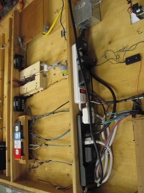
Seems like there is nothing standard about all these power supplies. Each kit or add on piece that required power came with it's own supply. This module deals with the multiple supplies at different voltage/DC/AC/Amps. (5) different wall warts pictured, and some of the accessory animation is 110 volt. 
Access to this requires an OGR Forum Supporting Membership


