Hi everyone,


Could someone tell me which component of a TIU Rev L. is damaged when the following electrical behavior is observed:


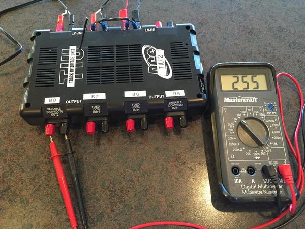
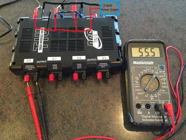
As per the images attached, the channel VAR 2 Out is converting the AC input from a Z-4000 to DC (!?!?).  This is obvious when analyzed with an oscilloscope, but it makes a normal meter (in AC mode) showing a "weird voltage" of 55 Volts.


(BTW, This is the situation that was reported in post:  https://ogrforum.ogaugerr.com/t...388#9595974411703388 , but that post is locked for additional replies)


Here are the images:


Channel FIX 1 Out ==> Normal:

Fichier 15-11-24 07 49 33


Channel FIX 1 Out ==> Normal:

Fichier 15-11-24 07 47 51


Channel Var 2 Out ==> Something is broken!   what component(s) ??? ) (Somehow getting DC Output)

Fichier 15-11-24 07 50 56

Channel Var 2 Out ==> Something is broken!   what component(s) ??? ) (Somehow getting DC Output)

Fichier 15-11-24 07 49 07


Thanks,

Daniel


Attachments

Images (4)
  • Fichier 15-11-24 07 49 33
  • Fichier 15-11-24 07 47 51
  • Fichier 15-11-24 07 50 56
  • Fichier 15-11-24 07 49 07
Last edited by Daniel Auger
Original Post

Replies sorted oldest to newest

Originally Posted by Moonman:

Why have you jumpered Fixed 1 in & Fixed 2 in?

Simply to bring EXACTLY the same power source to ALL INPUTs.  This ensures that the reading differences at the OUTPUTs are not caused by any différences at the INPUTs, but is only the result of the TIU electronics doing something (like converting AC to DC on VAR 2 out)

Originally Posted by GGG:

What is your power source going into VAR2?   Since have you tried a different Power Source such as the one used on Fix1?


I don't know what could fail and take a 18VAC source and boost it to a x? Volt DC source.  I can't believe it is really 55Volts.   G

Different AC sources were tried (Z-500 and Z-4000).  Same results.  All INPUTs are connected to EXACTLY the same source.  The 55Volts is what the meter is reading in AC-mode, but in fact it is DC, so the reading is "wrong", here is what the meter read in AC-mode and DC-mode:


Reading in AC-Mode: 55.5 Volts (Meter reading is wrong because signal is DC somehow)(

Fichier 15-11-24 07 50 56

Reading in DC-mode:  25.5 Volts

Fichier 15-11-24 07 51 39

Attachments

Images (2)
  • Fichier 15-11-24 07 50 56
  • Fichier 15-11-24 07 51 39

I was going to recommend a load too, but I am still baffled how the O scope is showing a high DC signal.  Shorted FETs may give you a constant high output but I don't think it should be higher than the input source or at least not by a significant amount.


Maybe the FETs have shorted such that you have them acting as a rectifier and only passing the + half of the sine wave AC input resulting in a DC like output.  Otherwise U would have thought you would just see the AC signal passed through but still AC in nature.  G

Last edited by GGG

In AC Voltage mode, swap meter's red/black leads to the TIU output.  Some hobby meters make AC measurements by simply looking at the "positive" voltage and doubling it.


Then do what Dale suggests and put a lock-on or similar load.  Any capacitance in the TIU output will "hold" the voltage since there is essentially no loading from a meter or scope.


I suspect you have a stuck-on/shorted FET as GGG suggests.  Without the benefit of schematics it would be challenging to troubleshoot. I suppose you can get lucky and try replacing any visually damaged components if you can see any.

Hi everyone,

Thanks for your replies. 

Based on the information received, I will go ahead and replaced the 4FETs feeding VAR 2 Out.  If anybody knows the exact FET model that I have to order, please let me know.  Otherwise, I will find out when I remove the old ones. 

If replacing those FETs correct the problem, it will prove that these can fail in a way that they start acting as a rectifier somehow.  This would also solve the mistery of post https://ogrforum.ogaugerr.com/t...388#9595974411703388 reporting the same problem, but with no solution.

Daniel


Last edited by Daniel Auger

If you have one bad channel, why are you replacing 4 FETs?

1.  You should redo the scope test with a load.

2.  You should use your volt/ohm meter on the "diode" setting and probe the FETs.  You can compare the readings on the good channels with the bad channel to determine if one or both FETs on the bad channel are shot.

Dale Manquen posted:

If you have one bad channel, why are you replacing 4 FETs?

1.  You should redo the scope test with a load.

2.  You should use your volt/ohm meter on the "diode" setting and probe the FETs.  You can compare the readings on the good channels with the bad channel to determine if one or both FETs on the bad channel are shot.

I do not have any schematics, so I go with the information I have... So, from the information I got, the total of 8 FETs are:

4 FETs for VAR1

4 FETs for VAR2

If someone has other information, you are absolutely welcome to share and contribute.

Thanks,

Daniel


Last edited by Daniel Auger
stan2004 posted:

If you "do" eBay and are in no rush you can find good deals on FETs...

Untitled

Thanks for the information !

I get from your message that all 8 FETs are identical.

There seems to be two versions.  Is there one preferable to the other one ?

Versions:

http://www.vishay.com/docs/91291/91291.pdf

http://www.vishay.com/docs/91292/91292.pdf

Thanks,

Daniel

Last edited by Daniel Auger
RJR posted:

Personally, I think you're jumping the gun.  I have observed this condition, or one similar, once or twice over the years, and tried a different meter. 


Apart from these crazy readings, how do the trains run?

Here are the observations to help clairify things:

1) First, let`s forget about the meter.  The osciloscope reading can`t lie, and it clearly shows that the VAR 2 out is pushing a DC signal, while all other channels are pushing an AC signal, even if all INPUTs are on EXACTLY the same AC source (Z-500 or Z-4000).  If I put the meter reading picture in my post, is was simply to make a link with the other "Weird" post mentioned above.  I do know that I am NOT getting 55 volts AC.  The meter is just "confused" because the signal is somehow DC, as shown by the osciloscope.

2) This issue was found because of trains behaviours problems.  So, to your question "how the trains run ?", here are the observations:

a) For the one LIONEL loco I tried, it just does not move. It works fine on the other TIU channels.

b) For the MTH locosss (many tried), it does move normally, but the DCS signal is unreliable, or not working.  It works fine on the other TIU channels.

These two observations (problems) are the reasons why a meter and an osciloscope were put on the TIU.

Hope this clarify things,

Daniel


Last edited by Daniel Auger

First I still don't understand the 2 sets of power leads feeding Input 2.

By enlarging the 1st picture it appears that your jumper is incorrect, that is Fixed one Red is feeding fixed 2 Black and vice versa. That would certainley lead to a false output reading and a bad sine wave.

That sine wave doesn't look right anyways as a Z4000 produces a chopped sine wave and the TIU chops it again. That sine wave pic is to smooth.

Since your cheap meter isn't a True RMS (Fluke) meter then switch it to read a DC waveform as that's obviousley what you have.

I think the OP has abandoned the meter reading issue.  As I mentioned above, this is/was probably due to the AC measurement "technology" used in his meter.  For example, I'll bet if he took a 9V battery and measured it in AC-mode it would read 18V (or so) in one polarity and 0V in the other.  Try it on YOUR meter...you may be surprised (or horrified)!


stan2004 posted:

I think the OP has abandoned the meter reading issue.  As I mentioned above, this is/was probably due to the AC measurement "technology" used in his meter.  For example, I'll bet if he took a 9V battery and measured it in AC-mode it would read 18V (or so) in one polarity and 0V in the other.  Try it on YOUR meter...you may be surprised (or horrified)!


Yes, thanks Stan2004. Please, let`s all forget the meter reading... it is unfortunately and obviously confusing the topic, and that is not the point here.

The point is that the TIU is damaged and trains do not run normaly anymnore on VAR 2 Out.  "Coincidentally", the Output on VAR 2 is abnormal, as shown on the ociloscope (DC) and on my "cheap" meter ;-)

I will order the FETs is a few minutes, and share the results next week.

Last edited by Daniel Auger
Casey Jones2 posted:

First I still don't understand the 2 sets of power leads feeding Input 2.

By enlarging the 1st picture it appears that your jumper is incorrect, that is Fixed one Red is feeding fixed 2 Black and vice versa. That would certainley lead to a false output reading and a bad sine wave.

That sine wave doesn't look right anyways as a Z4000 produces a chopped sine wave and the TIU chops it again. That sine wave pic is to smooth.

Since your cheap meter isn't a True RMS (Fluke) meter then switch it to read a DC waveform as that's obviousley what you have.

1) Here is how the connections are done at the input.  There is no mistake on the input connections. (i.e. the black and red are NOT mixed)

Fichier 15-11-24 07 50 56 Jumpers

2) For the "sine wave" shape comment:  I took a picture of what the ociloscope was showing, but it is true that a Z-500 was the source of power at the picture time (not a Z-4000). 

I do not have a picture with the Z-4000, but the general result was exactly the same: i.e.  It is AC-sine-shape on all channels, except VAR 2 Out (Strait DC).


Attachments

Images (1)
  • Fichier 15-11-24 07 50 56 Jumpers
Last edited by Daniel Auger

Hello everyone,

As advertised last week, I have replaced the 4 FETs driving the VAR 2 Out, and the problem is now fixed.

The VAR 2 Out is back to normal with an AC signal, like all other outputs.  (see pictures below). 

The train tested is running good too, with good DCS signal on all TIU channels.

Conclusion:  The "DC" problem has been fixed by replacing the 4 FETs.  I can`t tell if 1,2,3 or all 4 FETs were damaged, as I simply changed all 4 FETs in one operation.

Thanks to GGG and Stan2004 for guiding me to the FETs.  That is really appreciated.

Daniel

Fichier 15-12-07 22 44 23Fichier 15-12-07 22 44 45Fichier 15-12-07 22 45 02


Attachments

Images (3)
  • Fichier 15-12-07 22 44 23
  • Fichier 15-12-07 22 44 45
  • Fichier 15-12-07 22 45 02
Daniel Auger posted:

Hello everyone,

As advertised last week, I have replaced the 4 FETs driving the VAR 2 Out, and the problem is now fixed.

The VAR 2 Out is back to normal with an AC signal, like all other outputs.  (see pictures below). 

The train tested is running good too, with good DCS signal on all TIU channels.

Conclusion:  The "DC" problem has been fixed by replacing the 4 FETs.  I can`t tell if 1,2,3 or all 4 FETs were damaged, as I simply changed all 4 FETs in one operation.

Thanks to GGG and Stan2004 for guiding me to the FETs.  That is really appreciated.

Daniel

Daniel, thank you very much for posting your FETs  replacement.  After testing 24 TIU Outputs there was one Output with 21 DC volts out with 17.5 AC volts Input.  When tested there were only 2 bad FETs (part # IRFZ44N)and I went ahead and replaced all 4 in that Variable 2.

I have no idea how the DC voltage might have been affecting the signal output.


Add Reply

Post
The DCS Forum is sponsored by

OGR Publishing, Inc., 1310 Eastside Centre Ct, Suite 6, Mountain Home, AR 72653
800-980-OGRR (6477)
www.ogaugerr.com

×
×
×
×
Link copied to your clipboard.
×
×