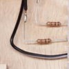
A little advice is needed please from the electronics experts out there.

I have a pair of LED Grade Crossing Signals (they are from Model Power)  that came with flashers installed. The flashers are random and not prototypical of how grade crossing lights should look. I bought a flasher board from Circuitron (the FL-2 board) to upgrade the signals to flash in sequence.

I need to add resistors to the LED's in the signals when I re-wire them and I am not sure what size to use. I do not know the rating of the LED's in the signals .

Any assistance would be appreciated.

Bob

Last edited by RSJB18
Original Post

Replies sorted oldest to newest

From the instruction PDF...

The LED Limiting Resistor Values in Ohms limits the current to about 12 ma. So it's depending on the voltage...use Volts/12 ma = resistance

For example if you power with 12 volts AC or DC (observe polarity), then 12 V divided by 12ma = 1000 ohms or 1K ohm resistor and rate the resistor at 1/2 watt.

gunrunnerjohn posted:

Chuck, I use a screen capture program called Snag-It.  I just snap the picture of a piece of the PDF, and then copy it directly into the post.  Works great and is very quick.  You can do the same with most any screen capture application.  Note that the picture of the table is a graphic, that came right off my screen.

Oh...dumb me. I have one called "snipping tool" that was buried on the tool bar.

Here's what it did...

Table

How about that?

Thanks so much John!

Attachments

Images (1)
  • Table

Well, the way I read the instructions, they tell you to put a single resistor in the COM lead and tie the other side of the LEDs directly to the L and R terminals.

It looks like you have done it differently, you have 2 resistors, but I can't see for sure all the detail due to the tie wrap holding all the wires together. I'd review your wiring, do it in accordance with the instructions and see what happens. I'd also verify the polarity of the LED connections, strange things can happen in common return circuits if they are mis-wired.

 What are you using as a power supply?

Attachments

Images (1)
  • mceclip0
Last edited by PLCProf
gunrunnerjohn posted:

If the relay isn't bouncing, it's something about that flasher circuit.  Since I have no idea how that's designed, I can't really offer any more insight.

Thanks for the reply John. No the relay is fine. I will play around with it some more. Not the end of the world if I leave it the way it is. I may check with Circu-tron also.

Bob

stan2004 posted:

Also, did you end up going with 1000 ohm resistors?  I was trying to confirm the color bands on your resistors but can't quite make them out.

2017-04-09%2011.16.06

Stan- yes they are 1K ohm 1/2 watt resistors. I am using 12VAC from the accessory terminals on a CW-80 to test.  On the layout I have a KW. In slow-mo I see both of them lighting up. Good catch, I didn't notice that.

Bob

It even appears there are intervals when both LEDs are OFF.  And intervals when one or the other LED is at some fraction of full brightness.  As described by their own literature the digital timing circuit should alternate with one and only one LED on at any given time...and when an LED is "ON" it should be full ON. 

While it would take a few minutes to troubleshoot using a scope, I figure you don't have one.  So I suggest you ask the manufacturer and maybe provide a link to the video.  This is a very curious behavior for a relatively simple circuit.  I understand just letting it be, but if you choose to dig deeper please let us know any discoveries. 

stan2004 posted:

It even appears there are intervals when both LEDs are OFF.  And intervals when one or the other LED is at some fraction of full brightness.  As described by their own literature the digital timing circuit should alternate with one and only one LED on at any given time...and when an LED is "ON" it should be full ON. 

While it would take a few minutes to troubleshoot using a scope, I figure you don't have one.  So I suggest you ask the manufacturer and maybe provide a link to the video.  This is a very curious behavior for a relatively simple circuit.  I understand just letting it be, but if you choose to dig deeper please let us know any discoveries. 

I contacted Circutron this morning and I have them stumped too. They suggested powering the board with DC instead of AC so I am going to try that and see how it goes. I am going to get the other cross buck set up also to see if it is a load (or lack of) issue.

Thanks

Open note to GunRunnerJohn and Stan2004-

I figured out the problem. THE LED'S IN THE CROSSBUCKS FLASH BY THEMSELVES

I ran 12VDC directly to the signals and the LEDs were blinking away happy as could be. Guess I need some new one's now. I will let the service tech from Circutron off the hook now too.

Just to verify my test, I hooked up a couple of LED's that I know do not blink to the board and relay and they work perfectly.

Thanks again for your help.

Bob

gunrunnerjohn posted:

Obviously, you have the flashing LED's, where what you need are the plain LED's.

Would be nice if Model Power had better specs for their products. I did remove a small flasher (I thought) module- must have been an alternating relay,  from the bottom of the sign posts when I took them apart. Chalk this up to experience. If everything worked the first time we set it up we would have our layouts done in 5 minutes.

Guess I have some lights for fire trucks and radio towers now too!

Thanks again. Bob

Last edited by RSJB18

Add Reply

Post

OGR Publishing, Inc., 1310 Eastside Centre Ct, Suite 6, Mountain Home, AR 72653
800-980-OGRR (6477)
www.ogaugerr.com

×
×
×
×
Link copied to your clipboard.
×
×