
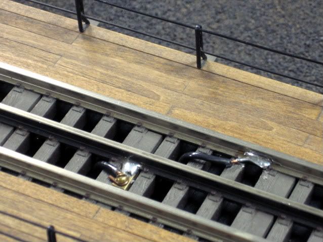
In the soldering of the tracks feeders to the rails I have experienced an issue with the clearance of the wheel flange of steam locomotive striking the soldered feeder wire joint while at the same location their is no clearance issue with the wheel flange of a diesel locomotive. Although the difference is minimal in flange height, the deeper flange height of the steam locomotive required the desoldering, lowering of the track feeder and soldering of one of the outside neutral track feed wires.

Their is no issue with the center(hot) rail as long as the feed wire is soldered to the rail web at rail mid-height, if possible solder the neutral track feeders to the rail web outside of the track gauge, no wheel flange interference  will occur, prior to the mounting the track to the board. I solder track feeders once the track is mounted, based on the track orientation, one outside(neutral) rail will have the track feeder soldered outside of the track gauge, the other outside(neutrall) rail has the track feeder soldered to the track web within the track gauge and the center(hot) rail is soldered in the same outward direction. Note, all three soldered joints are on the track webs facing you.  The flange height that must be cleared is determined by subtracting the wheel rim diameter from the wheel flange diameter and divide by 2, using this flange height to locate the solder position of the track feeder plus some clearance. 


Original Post

Replies sorted oldest to newest

I did this on the Fort Pitt Highrailers' turntable.  Atlas track, soldered low on the flange, both ends of the TT.  The center rail connections (2) are disconnected for transportation.  The bridge is removed and boxed separately.

Solder to the outside of the rails in most cases maybe the easiest.

The only track this does not work with is atlas:

Flip the track over, use a small flat screw driver and work it into the gap on the bottom of the rail. 

using a dremel with a burr (not a wire wheel) clean up the area you just put the screw driver in, being careful to not go through the rail, but get the surface clean and roughened.

Tin a wire then hammer it flat.

Put wire in rail.

Solder the wire in.

The end result is invisible, and nothing can hit it.


For atlas, I drill a hole in the rail, clean up around it, put the wire in and solder the hole shut. 

To expand on what the gentleman from Indiana said:

Boilermaker1 posted:

Tin a wire then hammer it flat.

Trim the wire back to about 3/8" after flattening

IMG_20160827_102356787.

Boilermaker1 posted:

Flip the track over, use a small flat screw driver and work it into the gap on the bottom of the rail. 

using a dremel with a burr (not a wire wheel) clean up the area you just put the screw driver in, being careful to not go through the rail, but get the surface clean and roughened.

IMG_20160827_115417528

Boilermaker1 posted:
Put wire in rail.

Solder the wire in.

Add a wire to tie the outside rails together. (Helps with Legacy/TMCC and DCS)

IMG_20160827_115452634

Steve

Attachments

Images (3)
  • IMG_20160827_102356787
  • IMG_20160827_115417528
  • IMG_20160827_115452634
Last edited by L & N
rattler21 posted:

Or use spade connectors forced into the rails from below without spreading them with a screwdriver.  John in Lansing, ILL

Until someone crawling under the layout yanks one out ... which is why we always solder them to the underside, melting a solder slug into the space with the wire, which flows into the hollow rail and makes a plug which cannot be pulled out from below by accident.

Add Reply

Post

OGR Publishing, Inc., 1310 Eastside Centre Ct, Suite 6, Mountain Home, AR 72653
800-980-OGRR (6477)
www.ogaugerr.com

×
×
×
×
Link copied to your clipboard.
×
×