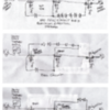
I have a MRC Pure Power Dual handle 270W transformer, where I was only getting 7V max output on one side of the transformer.  Put a scope on the 7V side and only saw the bottom side of the sine wave.  I pulled the cover and there was a circuit board with two rows of 6A10 diodes with 6 diodes in each row (each handle on the transformer has a circuit board with 12 diodes).  On the 7V side, one row of the 6A10 diodes, had a bad diode and another had come disconnected from the circuit board.  I replaced & resoldered the diodes and all is well now and I am getting the full 19V output.  


If someone could explain:

-Why is the 19V AC output of the transformer affected by the bad diodes? 

-Aren’t the diodes used for whistle & horn functions? 

-Why are twelve 6-amp diodes needed?  My old ZW has one diode.


Appreciate the education on this topic.


Thanks,


RAD400


Original Post

Replies sorted oldest to newest

The MRC transformer does the DC offset in a totally different way.  The power always goes through the diodes array, the two back-to-back sets of diodes are there to pass the full wave AC.  When either the whistle or bell button is pressed, five of the six diodes in one side of the diode strings are shorted so that there is about a 2.5V DC offset generated on the output power.


Each handle has the same arrangement of diodes as there are two sets of whistle/bell buttons.


There is not a boost winding in the modern transformers like the old PW transformers.


Originally Posted by gunrunnerjohn:

The MRC transformer does the DC offset in a totally different way.  The power always goes through the diodes array, the two back-to-back sets of diodes are there to pass the full wave AC.  When either the whistle or bell button is pressed, five of the six diodes in one side of the diode strings are shorted so that there is about a 2.5V DC offset generated on the output power.


Each handle has the same arrangement of diodes as there are two sets of whistle/bell buttons.


There is not a boost winding in the modern transformers like the old PW transformers.


John - Is there some where on the WEB I can see a wiring diagram showing what you described?  I am trying to visualize a set of diodes passing a full sine wave.


The need for 2 strings of 6 diodes, is one string for the horn and the other for the whistle?


Thanks again,


Thanks,


Rad400

Don't make it complex, just think of two diodes back to back with polarity reversed.


They will pass a full-wave AC signal minus only the diode drop as a half-wave is passed by one diode, and when the polarity is reversed on the other half cycle, the other diode passes it. 


The six work exactly the same way, only there is about a 3-3.5 volt drop instead of one diode drop as there are six diodes in each direction.


Now, if you short five of the diodes in one direction out, the drop on one half-wave is only one diode drop, but on the other half-wave it's still six diode drops.  The difference shows up as a DC bias on the AC waveform, which is what triggers the whistle or bell.


John, 

I want to be sure I'm understanding this correctly, just out of curiosity...

In this set up, the transformer's output is always cut by (about)3.5 volts, then when the whistle/bell is pressed, that half of the wave gets (about) the full voltage while the other half remains lowered, and this creates the DC offset needed for trigger the whistle/bell on the locomotive.  Does this replicate increasing the voltage as an old style transformer would, or am I thinking wrong here?  

You pretty much have it John.  The old PW transformers actually boosted the AC by around 6 volts with the boost winding at the second step of the whistle switch.  This was to account for the current draw of the whistle motor, the PW tenders sucked up lots more power than modern electronic whistles.  The modern transformer maintains the same AC power and just adds the DC offset.  I suppose, depending on the specific locomotive electronics, that you could get a slight boost in speed from the DC offset being added.  It'd nothing like the old PW transformers, but a small effect is doubtless there.

Originally Posted by gunrunnerjohn:

Don't make it complex, just think of two diodes back to back with polarity reversed.


They will pass a full-wave AC signal minus only the diode drop as a half-wave is passed by one diode, and when the polarity is reversed on the other half cycle, the other diode passes it. 


The six work exactly the same way, only there is about a 3-3.5 volt drop instead of one diode drop as there are six diodes in each direction.


Now, if you short five of the diodes in one direction out, the drop on one half-wave is only one diode drop, but on the other half-wave it's still six diode drops.  The difference shows up as a DC bias on the AC waveform, which is what triggers the whistle or bell.


John


Thanks for the update, I am on board with the 4 diodes explanation you gave. When MRC uses the 12 diodes combination, is that done so a different DC value can be sent to the engine to distinguish between horn & bell.


Thanks,


Rad 400

Add Reply

Post

OGR Publishing, Inc., 1310 Eastside Centre Ct, Suite 6, Mountain Home, AR 72653
800-980-OGRR (6477)
www.ogaugerr.com

×
×
×
×
Link copied to your clipboard.
×
×