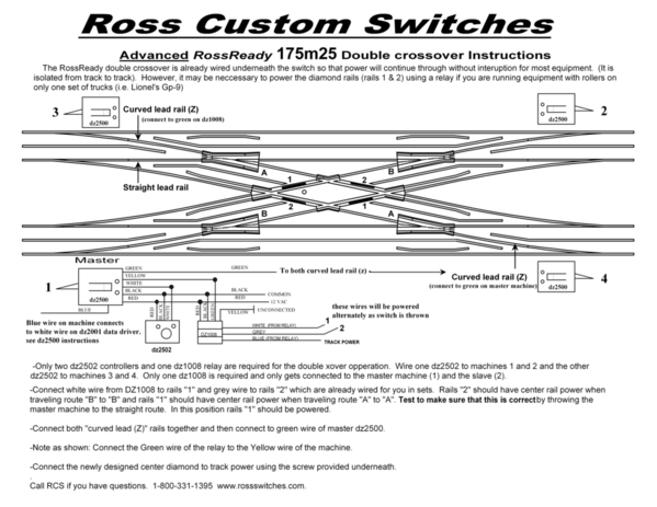
I am trying to wire an O Gauge 3 rail Ross double cross over using 4 Gargraves DZ 1002 Switch Motors and a Gargraves DZ 1008 relay. This the second $60 switch I have tried to wire. The directions from Ross begin by saying that because of the length between the center black rails we have imbedded 4 short black center rails  into diamond of the 22.5 Deg Xing. and to use insulated rails powered by a DZ1000 Switch machine and  a DZ 1008 Relay. A friend a substituted wiring instructions for a DZ 1002s and I am comfortable with that.

Then the directions go on to say that the crossing comes from the factory with the 1 and 2 rails connected in sets. ( the #1 rails are depicted in black on the left an right rails of the Y rails thru the diamond and the # 2 rails are depicted as right and left rails of the Z rails thru the diamond. ) and goes on to say drop a wire down from each of the two wires that form an X on the bottom of the crossing and connect the grey wire from the DZ1008 to rails #1 and rails #2 to the white wire of the DZ1008.

Ergo my problem the Rails #1 and #2 depicted in black on the diamond are plastic with no apparent wire to connect to!!!!!! I asked Steve Ross to wire the crossover and it came with 4 GREEN Wires connected to  both  common rails 1 and 2 at the end of the cross over some distance from the diamond. The directions go on to say to connect the insulated rails Z together and connect them to the green wire of the Dz1008 and the to connect the insulated wires Y together  and connect them to the yellow wire of the DZ1008 I can do that.

The whole point of the wiring is so that the switch buttons send power to isolated Z direction when the switch is thrown thru the diamond and vice versa for the Y direction thru the diamond, other wise you have sparks. My 72 year old brain can not figure out how to connect the rails 1 and 2 at the X of the diamond to the respective wires o the DZ1008  Please help

Attachments

Files (1)
Original Post

Replies sorted oldest to newest

Then the directions go on to say that the crossing comes from the factory with the 1 and 2 rails connected in sets. ( the #1 rails are depicted in black on the left an right rails of the Y rails thru the diamond and the # 2 rails are depicted as right and left rails of the Z rails thru the diamond. ) and goes on to say drop a wire down from each of the two wires that form an X on the bottom of the crossing and connect the grey wire from the DZ1008 to rails #1 and rails #2 to the white wire of the DZ1008.

I have the original double crossover that ross made and had to do my own wiring so here is the how to.

the diamond where ross shows a diagram of an X there are 4 short metal rails and unless ross has prewired these since I bought mine a good 15 or more years ago you have to add your own wires to all 4 of the rails on each side of the diamond these wires will provide the +/ power to the engines pickup rollers and must be wired in pairs so as engine crosses from outer track to the inner track the rails that the drive wheels contact are not powered as that would create a dead short.

now you can solder these wires while crossover is sitting on your work bench or you can use solderless spade connectors and insert the spade end into the small slit in underside of those rails. I used the spade method and no issues to date but this is your call as to connection method.

now the hard part all 4 wires have to remain separate and holes drilled in plywood or? roadbed used so use a colored tape or masking tape to identify one pair of wires that need connected as a paired set so that those wires  would control the power for a train to go from inner track to the outer track that way you will have both rails powered at that time as the other 2 rails will be dead other wise you will create a dead short if even one wire is paired incorrectly.

once you get this concept in ones head it all makes sense it took me awhile to get the light bulb in my own head to grasp it so don't feel bad as it is confusing at first.

if all else fails call Steve and he will walk you through it. unless I misread your post only the common rails have the 4 wires pre-wired for you?

in my day I had to do all of that myself so consider the pre wired ross switches of today as a plus as I had to wire it all and not being an electronics fella took many a day to figure out how to wire 12 volt relays and switch machines so all worked correctly when toggle switch was set to go from outer to inner track.

hope this helps you.


Last edited by StPaul

Have you tried trying the 1 to 1  together  and then 2 to 2 together yet ?

After that trying Z to Z together  Y to Y  together.  See if that's correct your wiring problem.  Please try using alligator clips to you get it figure out.

That's what the wiring Diagram is showing me here.

Kb2agpjohn@aol.com  should need  contact me

Good luck , John      


There are no bear track on any side of the diamond that I can find or see. Perhaps he section on the diagram that deals with "you may have to power these embedded rails with a dz1000 and a 1008 relay'.  maybe the directions for wiring  a Gargraves switch machine with direction wires will solve the problem? However the Ross directions specifically go on to describe how to connect the 4 wires on the x to the relay. Does the embedding of rails mean that you can power the x at some other contact point?

Attachments

Dear Greg referring to your switch machine could I run my wires to the 4 silver rails that join the plastic x since ross says that the rails are embedded thru the crossover? But that is confusing because the switch machine motors are connected to the same rails. maybe the dz1008 separate the division of power for us


Syrabob posted:

Dear Greg referring to your switch machine could I run my wires to the 4 silver rails that join the plastic x since ross says that the rails are embedded thru the crossover? But that is confusing because the switch machine motors are connected to the same rails. maybe the dz1008 separate the division of power for us


I'm not really sure what Crossover you're using but keep in mind the center rail rollers are going to roll over a borrowed outside rail which   now becomes hot to extend the center rail  pickup  range  via  the relay.    Can you put a pic up?

SYRABOB and Gregg  yes the diamond is plastic only the middle part that looks like a diamond but do you both see those short pieces of rail that is in direct line with the middle rail on either side of diamond those short rails are not plastic they are metal but are darkened just like the third rail/ middle rail of track.

trust me I have the exact same ross double crossover that Gregg posted if needed go to browser view settings and set zoom to 300% that will show you those 4 small rails they are there!

do you see them now?

Last edited by StPaul

see the above diagram see the diamond do you see those 4 darkened areas next to 1 - 1 and  2 - 2 those are not plastic those are the metal rails that need positive power so when engine crosses them the power pickup rollers get power to get across the plastic center area of diamond. now does it make sense?

while I am at it the rails marked A and B also need positive power to them preferably from same power source as lead tracks coming to track just prior to entering where the diverging route will happen if set to leave either inner or outer mainlines.

if I lived in your area I would gladly come to your home and help but this is best I can do.

Attachments

Images (1)
  • blobid0
StPaul posted:

SYRABOB and Gregg  yes the diamond is plastic only the middle part that looks like a diamond but do you both see those short pieces of rail that is in direct line with the middle rail on either side of diamond those short rails are not plastic they are metal but are darkened just like the third rail/ middle rail of track.

trust me I have the exact same ross double crossover that Gregg posted if needed go to browser view settings and set zoom to 300% that will show you those 4 small rails they are there!

do you see them now?

Yep I see them now. Thanks...

SYRABOB 

now I understand as we all thought from your post you were using a  ross ready double crossover when in fact your using a ross 30 degree crossover with 4 separate switches this is a new ball game! below is ross diagram on how this diamond is powered using a double pole double throw toggle switch.

 why didn't you buy a ross double crossover as with the 30 degree and switches am thinking it is wider than the pre made one sold by ross, or is it a monetary and or you had these switches laying around or your track plan is wider than the spacing of the pre-made ross double crossover?


here is the wiring diagram for a ross double crossover basically you wire a dz-1002 switch controller to the dz-1008 relay then the grey wire to 2 dz-1000 switch motors and in your case to only one rail embedded into the diamond, also rails B and A need same power as embedded rails 1 and 2 so when you select route all rails coming off of mainline then entering the curved leg of switch engine will have power from B to embedded rail to opposite side of diamond.

then the white wire goes to the other embedded rail on your 30 degree crossing. you also connect track power to the blue wire of dz-1008 relay so that what ever route you choose the power is sent to the correct embedded rail.

then when all is powered up the dz-1002 controls what diverging route you select and will kill the power to the other embedded rail. far as I can see the center of the diamond is not powered at all only those 2 embedded rails are powered.

does this make it clearer for you seeing both diagrams together?

Add Reply

Post

OGR Publishing, Inc., 1310 Eastside Centre Ct, Suite 6, Mountain Home, AR 72653
800-980-OGRR (6477)
www.ogaugerr.com

×
×
×
×
Link copied to your clipboard.
×
×