Dave_C showed me these on his layout and I just got done installing them on my layout. By far the best way to protect your trains.
More info,
http://amhobby.com/products/te...owershield_x_ac.html
Can be purchased at Train Tek for 35.00


|
|
Dave_C showed me these on his layout and I just got done installing them on my layout. By far the best way to protect your trains.
More info,
http://amhobby.com/products/te...owershield_x_ac.html
Can be purchased at Train Tek for 35.00
Replies sorted oldest to newest
Thanks Gary. Great info. Will be looking for them at York.
Gary, great video. Very informative.
I recently bought an Atlas transformer for a small layout I want to build and it literally takes 8 to 10 seconds to trip the breaker and this is with me tying the two wires that come out of the transformer directly together! I've got to get one of these breakers and set it for 8 amps like you did. Thanks a lot.
Thanks for the links Gary; may have to get myself two.
Nice demo Gary. I've been using these breakers for about four years now without incident. I too have them wired the same way, when it trips I have to reset it manually. I have had mine wired for 12amps from the start. When I first installed them I did a little testing myself. I pulled apart a two inch section of the 12ga. stranded wire I used to wire my track. With a single strand of that wire I shorted the track as Gary did. I expected a flash and puff of smoke but instead it tripped the breaker. Even with this sensitivity it does not trip from the bit of arcing I get from pickup rollers or when an engine passes through my Ross switches.
When you consider your investment in motive power, $35 bucks seems like chump change.
Milwrd
When you consider your investment in motive power, $35 bucks seems like chump change.
Your not kidding ![]()
Nice demo Gary. I've been using these breakers for about four years now without incident. I too have them wired the same way, when it trips I have to reset it manually. I have had mine wired for 12amps from the start. When I first installed them I did a little testing myself. I pulled apart a two inch section of the 12ga. stranded wire I used to wire my track. With a single strand of that wire I shorted the track as Gary did. I expected a flash and puff of smoke but instead it tripped the breaker. Even with this sensitivity it does not trip from the bit of arcing I get from pickup rollers or when an engine passes through my Ross switches.
When you consider your investment in motive power, $35 bucks seems like chump change.
Milwrd
Ditto, and thanks guys.
One thing I forgot to mention. You can add LED to your control panel and wire them to the PSX for the same indication.
great stuff
Even sent it on to some of my ho pards.
In regards to other scales, there's a DC version for them.
Gary, I assume these can be used running command or conventional? I have some TMCC Lock-Ons and while very fast they cannot be used with conventional equipment as they don't turn on until about 13 volts.
Pete
I don't see why not but to make sure I would ask AMhobby at the link above.
Thanks for the demo and link, Gary. I think I'll use them when I build my home layout.
Gary, nice demo. I'll have to see how video and stills are added to a post.
Question: Has anyone who has used these tried less than a dead short to test them? For example, if it's set for 8 amps, and you gradually increase the current to slightly exceed 8 amps, how long does it take to blow? With fuses and thermal breakers, they would hamdle say 8.1 amps for a very long time before they opened.
Gary,
Great technology Gary, thanks for the link I will definitely take a real close look at these, for my layouts. Can you use two or more tracks from the same PSX circut protector or is this just a one at a time track set up? If possible I would run this as a multipule track safety controller.
RJR,
If these are micro contolled engineering, the breaker should act immediately, no lag time or build up required. Which Gary kind of demoded, as he shorted the track out, little if no spark what so ever, no excessive build up permitted. Real nice piece of engineering in deed.
PCRR/Dave
Gary, nice demo. I'll have to see how video and stills are added to a post.
Question: Has anyone who has used these tried less than a dead short to test them? For example, if it's set for 8 amps, and you gradually increase the current to slightly exceed 8 amps, how long does it take to blow? With fuses and thermal breakers, they would hamdle say 8.1 amps for a very long time before they opened.
The best way I think of is to run two trains on one track with all my passenger cars and lighted cabooses. One of these days I'll try it.
You guys are welcome. Anybody want my left over seven amp fuses?![]()
None, I know they are the same price either two PSX1 or one PSX2
Great review Gary. I've used these for a number of years with great results. I have a good size layout with both TMCC and DCS. I power my layout with basically 2 , 12 amp power supplies. I use 3 TIU's. The layout is sort of a walkaround and the 3 TIU's are placed around the layout so basically the outputs of the TIU's which carry the signal have much shorter runs. What you can do is run the wires from the power supply to the input of the breaker. I use a strandard 12 gauge. You can then split the wire as it exits the breaker to the inputs of your TIU. One breaker can handle multiple channels on many layouts.
Could this be wired in to a ZW? To replace the circuit breaker, protect all 4 outputs.Would it handle that.It would need to be mounted externally that would be ok with me.
Brad
Brad, I assume you refer to the old postwar ZW. While I have not used these devices, I would offer a few thoughts. The internal ZW breaker is between the U terminal and one end of the transformer secondary winding. It offers no protection whatsoever to shorts between posts A,B,C,D, which can happen if they are at different voltage settings. I use external breakers and/or fuses on each of the A,B,C,D outputs for this reason. At $35 a pop, 4 of these devices would be costly.
Guys, you really need to check all the links and read all the info. For post war transformer guys check this out.
http://www.tonystrains.com/tonystips/2011/072811.htm
A very small price to pay to protect 1000 engines and to keep the arch welding of wheels to tracks to a minimum.
Gary,
This will be a lot more expensive than I 1st thought, it looks as if you must have a minimum of two of these PSX breaker units for each ZW, KW and Z4K transformers.
To cover my layout power, 2 ZW's, @ $35.00 x 4 = $140.00 + 1 KW, @ $35.00 x 2 = $70.00 + 2 Z4K's @ $35.00 x 4 = $140.00, = a total of $350.00 Plus 7% Tax =
374.50 to safe guard my complete layout with the PSX units, it will cost me about $400.00, use these PSX units. Great technology but not cheap for a fair sized layout.
PCRR/Dave
I'd check prices for electromagnetic breakers.
I want to build a small layout for my grandson. It won't hae a large control panel. What do you guys think would be the best way to mount the PSX so that the electronics are not exposed to the child?
These look great. As to the trip current, I think you would set it to the maximum of your supply for the most part...otherwise, why pay for that much available? Of course if you ended up with big supplies, and only need a few amps, then set it for 4.8 or 8. How about having a switchable setting...it looks like a 3 pole, 4 postition switch would allow you to sellect four trip settings on the fly. If you are only running one engine at the time, then set it to all jumpers open for the lowest current of 4.8 , etc.
a PSX2 is just 2 PSX1's still attached on the same PCB. From what I've seen in photos, it looks they're possibly made in groups of 4 at the foundry and separated at the etch lines if they want to do PSX1, 2 or 3. Its the same circuit layout put on the PCB multiple times with etch lines to separate them and break them off separately if one wishes, so theres no cost savings or advantage to buying a 2 or 3 unless you just want them all attached still.
Where is a picture of a multiple one?
cjack, except for the old Lionel transformers, the internal breakers should be (SHOULD BE) enough to protect the power supply. The issue is to protect the TIU and eqpt. Wires in cars can't take that much current (consider when they straddle the gap between 2 power districts, and one has a short), and in a derailment wheels & axles can get hot. Best practice to set to breaker to just above a normal load, but I wouldn't go above 10 amps for each TIU circuit.
Your suggestion to use a 3-pole 4-position switch is a very good one.
Thanks for the reply.
I have caused some pretty good frying on some of the layouts in our train running club. I was thinking that with this variable trip feature, we might be able to avoid some of the welding that has occurred. We could tailor the trip to what we are running instead of having to go the whole 20 amps in the case of the 400 watt TPC.
My new ZW does a pretty good job at tripping fast, but I think the PH and TPC have thermal breakers and take a bit of time...thus the arcing.
After my Y6b derailed over a turnout, there was a shower of sparks and blown fuse. At first the engine did not start up. Oh brown stuff I said. After a minute's rest and new fuse, Y6b restarted. So I ordered two of these breaker boards which came today and I will install tommorrow. Thanks for the video and info.
I have one & agree strongly. Very nice circuit breaker.
Gary, I assume these can be used running command or conventional? I have some TMCC Lock-Ons and while very fast they cannot be used with conventional equipment as they don't turn on until about 13 volts.
Pete
Has anyone used the psx equipment with conventional trains, or just with command control? I like the TMCC lock on for use with TMCC, but it doesn't work well when you switch to TPC control.
I haven't seen Norton's question answered yet. If the psx doesn't work well with conventional control, I don't see any reason to switch from the TMCC lock on. If the psx unit works well with conventional and command control, there is a reason to consider switching.
Kind of surprised reading instruction that they don't have a pot adjustment to fine tune the coarse jumper selection, ie set to 10 A or turn it to where it just trips then back off a quarter turn maybe.
Just a thought.
Gary,
This will be a lot more expensive than I 1st thought, it looks as if you must have a minimum of two of these PSX breaker units for each ZW, KW and Z4K transformers.
To cover my layout power, 2 ZW's, @ $35.00 x 4 = $140.00 + 1 KW, @ $35.00 x 2 = $70.00 + 2 Z4K's @ $35.00 x 4 = $140.00, = a total of $350.00 Plus 7% Tax =
374.50 to safe guard my complete layout with the PSX units, it will cost me about $400.00, use these PSX units. Great technology but not cheap for a fair sized layout.
PCRR/Dave
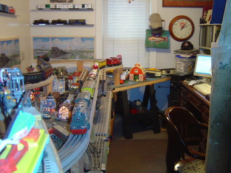
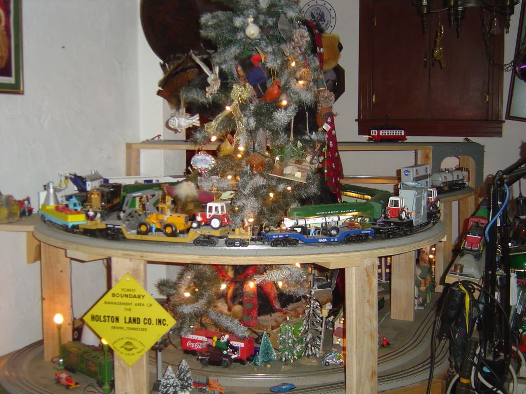
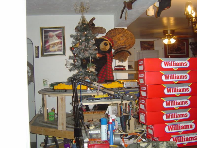
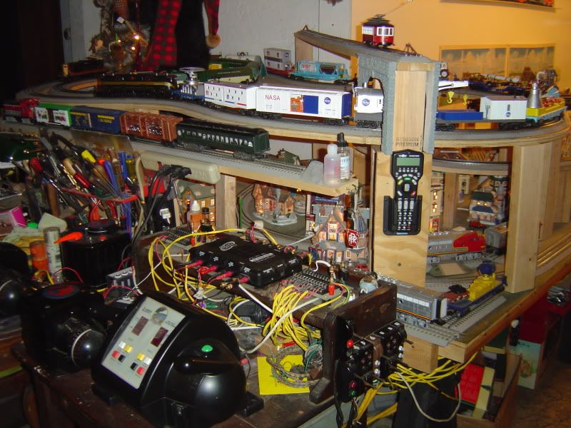
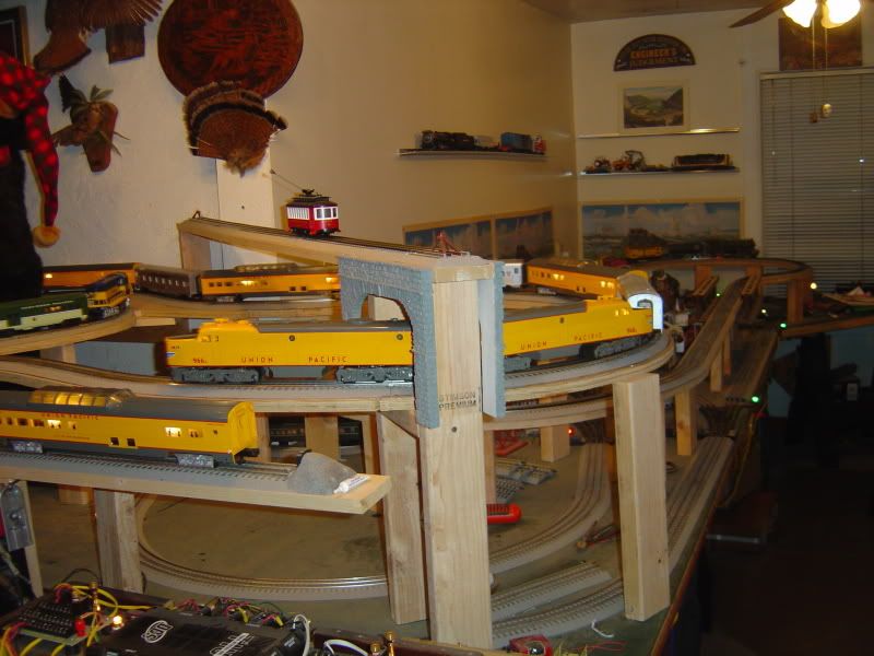
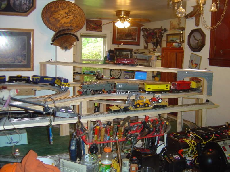
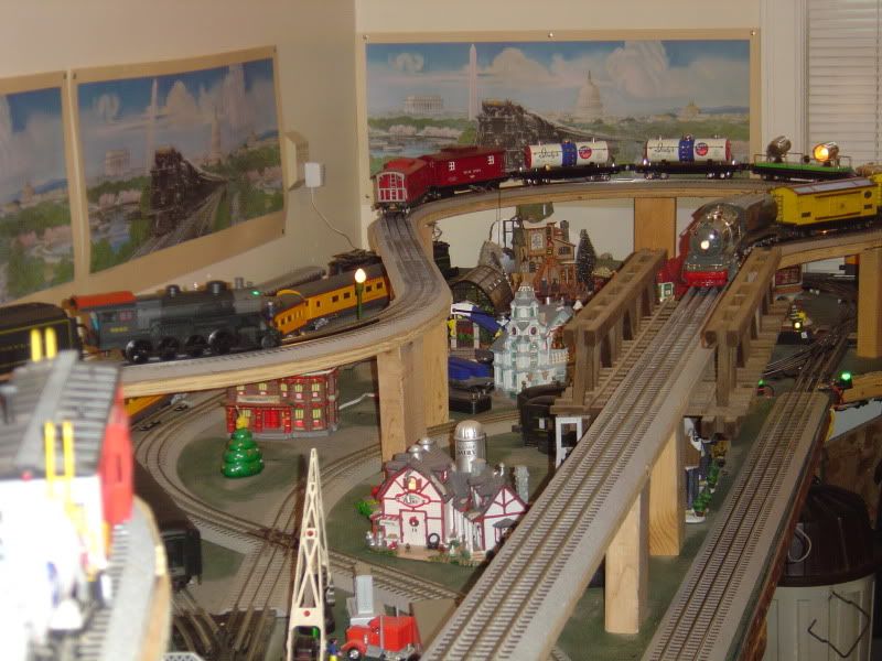
How large is your layout and how many tracks do you have? I have two main tracks, two scale miles of mainline and a yard and sidings. I could of gotten away with only one PSX but wanted each mainline to be independent of the other. Max current draw of the entire layout 10 to 12 amps running one passenger train(seven lighted cars) and three other freight trains for a total of five engines. I would think your layout is larger than fair size which I would love to see by the way. Are all those transformers just for running trains?
Conventional control is question that should be sent to AMhobby for a answer. I would like to know as the instructions don't really mention it. I would guess they would be ok but a expert would need to answer.
Update, I just sent a email to Traintek about everyone's concern. Hope to post answer tomorrow.
Gary,
Yes all those transformers were for running trains and a mess of old 072/711 Lionel Switches, which take serious power to work properly all the time. Wish I could have you over to see the layout, but we just took her down this past month. The layout was up for almost 5 years. There were 5 different levels and a programming track. About 9 tracks in all, completely DCS and Conventional. On each level there was a mess of lighted cars and some operating equipment. The layout was set up in a big L, that took up most of my office 16' and most of the 30' game room. It was impossible to get in one picture because of the two different rooms it covered. It was fair sized but nothing like Patricks big layout. My problem was the massive power draw, due to of the old Lionel switches, I am going to experiment with the new Ross Tin Plate 072 switches on my next layout. I like my Tin Plate and so far only the old Lionel 711 & 072 Lionel switches actually accommodate, all Pre War and new MTH Tin Plate.
Gary if I could make the PSX units run at least 2 track a piece, this would eliminate half the cost. I will need to investigate these PSX breakers further to see what they are capable of handeling. Thanks for the engineering info sir, I love the new technology,
it a grea way to safe guard the entire layout.
PCRR/Dave
Some pictures of the layout to give you an idea of it size.
Conventional control is question that should be sent to AMhobby for a answer. I would like to know as the instructions don't really mention it. I would guess they would be ok but a expert would need to answer.
Update, I just sent a email to Traintek about everyone's concern. Hope to post answer tomorrow.
Thanks for emailing the company and asking the question.
I've got to say that the electrical engineer in me is impressed by these. The reason these do not spark is that the response time of the circuit is so fast meaning that the time to detect the short circuit and shut down happens in a small fraction of a second.
Conventional control is question that should be sent to AMhobby for a answer. I would like to know as the instructions don't really mention it. I would guess they would be ok but a expert would need to answer.
Update, I just sent a email to Traintek about everyone's concern. Hope to post answer tomorrow.
Thanks for emailing the company and asking the question.
Believe the board electronics derives its power from the transformer input side as I don't recall seeing an auxilary power "keep alive" input connection in the instruction or looking at the board picture. That said, I don't know what the minimum input voltage would be and still have the board reliably function for short circuits. But could be a trade off of figuring if the input is at 5-6V then the damage is minimal compared to full throttle 18+V.
PineCreek: You mentioned that the old 072 switches draw a lot of power. Certainly the 18-volt bulbs in them do (Lionel used to say 5 watts each), but they can be replaced with alternatives. I suspect the magnets do draw power but it's only for an instant, so what's the problem?
Many decades ago, I used to have the Lionel #022 O-31 switches. Turns were too sharp, but cars never derailed going forward and operating cars never were triggered. I have switched to Gargraves O-100 & O-72 switches, and these are periodic problems. I suspect the O-72 switches (I forget Lionel's number) were just as good in that regard. I suggest you think about keeping the O-72 switches and think about rewiring them.
Access to this requires an OGR Forum Supporting Membership
