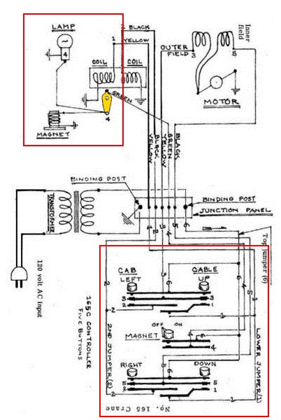
I rotated the schematic supplied by @ADCX Rob to make is easier to picture the contact layers in the controller. As I read the schematic, I agree with @David Johnston that the lamp only comes on when the magnet is turned on by the know in the middle of the controller - which seems to be missing in your picture of the controller - though you can see on of the contact bars for the magnet switch knob.
Anyways, I would assume that the contact layers shown in the schematic physically match how the controller is built. Thus, under the Cab Left button, there should be three contact bars ==> Top Contact bar to wire 6, Middle Contact bar to wire 3, and Lower Contact bar to wire 2. You proceed to each button, then the knob, making sure the proper wires get to the proper contact bars. This is one of those cases that if I could sit with you, use a Volt-Ohm-Meter to and soldering iron, we could figure this out in under an hour. Hope this is of some help.


