The four wires in the tether stay where they are connected. For the wires from the ERR RS Commander, you are going to connect them to the projecting pins where the sound board used to be plugged in. The sound board is to be removed along with the power supply board.
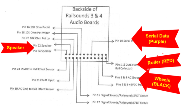
Connect the speaker wires to the pins on my diagram labeled Speaker.
Connect the black wire that comes from the ERR RS Board harness to the pins on my diagram labeled Wheels (BLACK).
Connect the red wire that comes from the ERR RS Board harness to the pins on my diagram labeled Roller (RED).
Connect the purple wire that comes from the ERR RS Board harness to the pin on my diagram labeled Serial data (Purple).