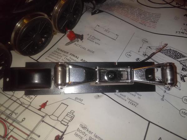
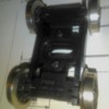
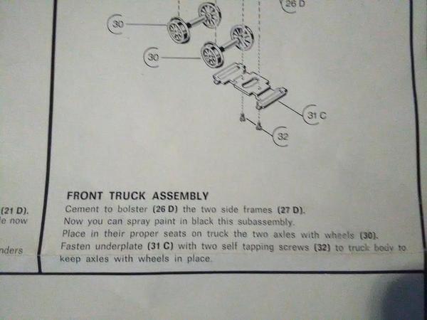
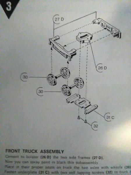
The last few days centered around the pilot truck working on Super Is 0-36 curves, but the assembly was simple. Glue the frame halves to the center guide, insert wheel sets, cover with bottoms and tighten two screws.
The drivrrs are hitting the fenders as is. I may trim the curved edge, making the diameter bigger or shim them out later, but I'm leaving those and the brakes off for now.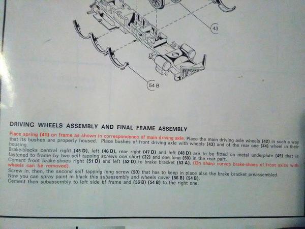
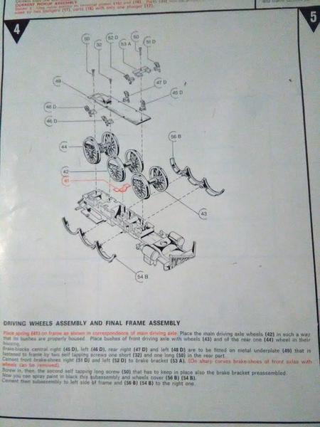
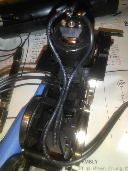
The short connecting rods added, along with the black metal guide plate, where I mounted the bridge rectifier for running the DC motor on AC voltage. Both are mounted on the same screw, alonger replacement from my own box o screws. The long rod and valve gear wait till I'm ready.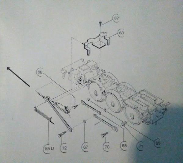
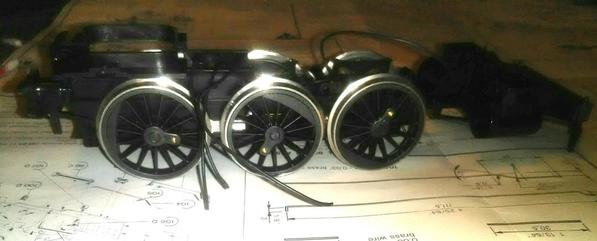
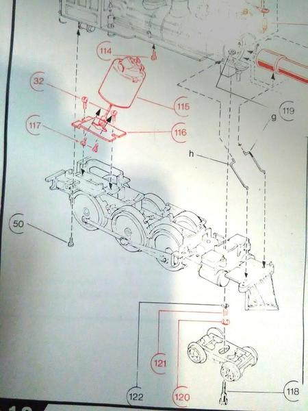
The mtors worm was MASHED against the axle gear once assembled. 2 washers under the plate at the rear mounting screw #32 gave a nice mesh. After a slight break in of twenty minutes as an 0-6-0 frame, one washer was removed. After another hour or two, I'll try to remove the other. Also note, the many holes for screws #117, within the motors end cap are in a spiral patten for universal mounting. You have to turn and align the motor position till two cap holes face to match the width of the two plate holes/slots. The red bar to the right is the ballast weight. The pilot screw #118 screws into a hole at the bars tip; but I assembled this differently for 0-36. A screw will hold the ballast bar there though, as you'll see next post.
I'm using a heavier wire from motor to bridge rectifier's + & - output lega than what was supplied..
It is a closer match to the donor GG-1 roller wire(variable, ~ input on BR) and closer to the combined dia of the 4 wheel plungers wires actually supplied, all combined into one "common"(com on BR ~ input)
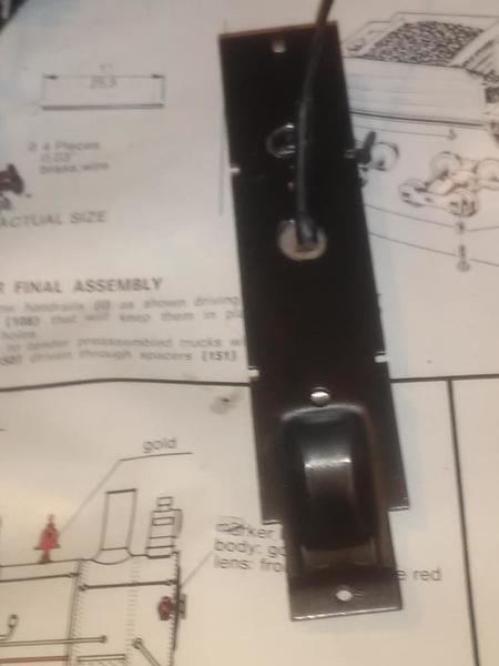
The gear/axle cover needed three holes drilled, stratigicly positioned fore and aft of a frame support. One small hole for an attaching screw, one large hole for the wire, one large hole for the centering tab. The centering tab was insulated with three layers of tape, stuck over the tab, but under the roller.; sandwiched.