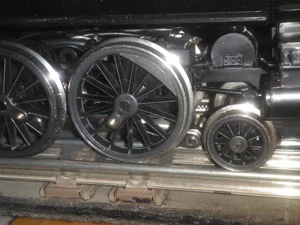
If you look into the frame near the lead drivers you can get an idea of how the bridge rectifier is mounted. The diode I had used to shave off 1.5v was removed. The motor likes over 12v just fine. It doesn't get as hot at 13.5 either. With the whistle circuit of the 1033 adding 5v, 18v sends it flying, minimal heat. The 0-36 pilot arm mod still needs to be added here, but pulls a few cars nice as a chassis...with some fishing lead to help weight.
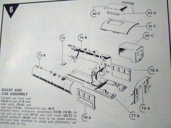
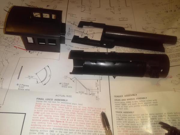
Ididn't from follow these instructions to the letter. I did it my own way again. I want it to be able to be disassembled for painting, service, and upgades, so the boiler/cab will remain unglued from the floor/boiler belly. But it was used to brace the cab was for.glue cure, then for the cab to boiler glueing too, just to keep the whole thing staight, greatly helping on assembly. My way it will need two to four floor level.plastic plates made to go in the cabs corners to receive screws up through the floor boards to the cab/boiler to.hold it on nice. That can wait, its really just to close toe seams better; it's solid enough for the most part right now.
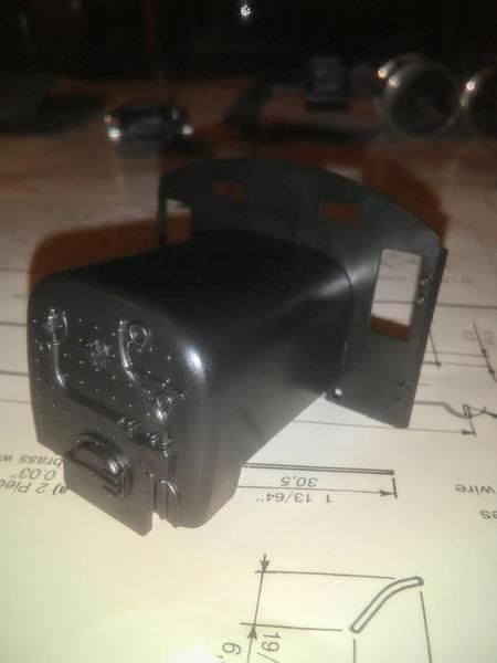
1st glued these two thickly. This area is going to have a nice strength to it when the other side gets the boiler too.
The blue tube, citrus based glue is slow curing.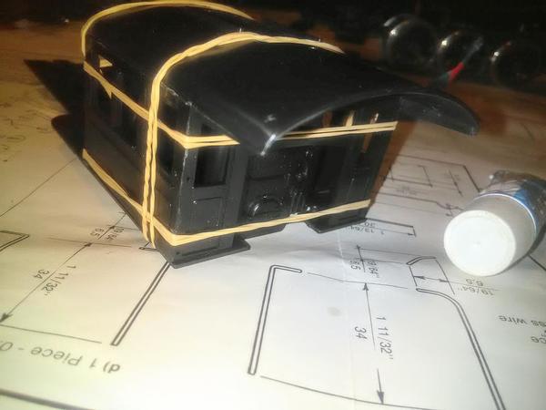
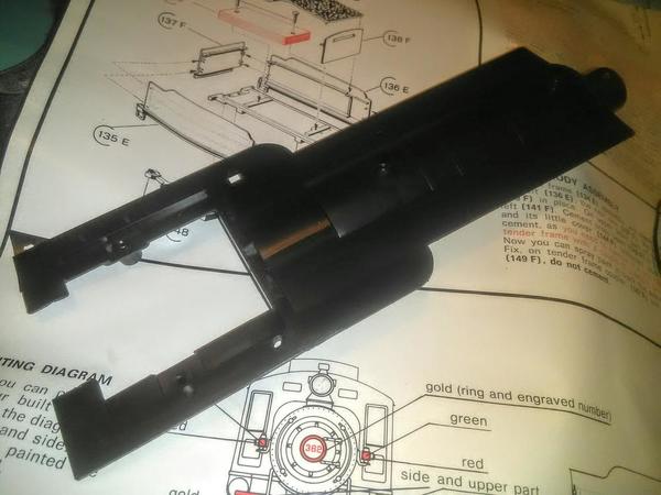
Note the ballst bar at the belly's tip. The tapped hole for the long pilot screw/post goes there. Halfway down the belly is machine screw holding the bar again there. The two bosses at the rear attach the frame later.