


It seems that, in my last post, some of the character sequences that I used turned into gremlins (emoticons). Colons and parenthesis will do that as I have learned. Also, when I cut and paste my program text into the edit screen, it looses the indentations. The format is still valid (minus the gremlins). Indentation is only significant to programmers, not the machine. The attached versions of the code remain unaltered and are available for anyone who wants to play with them.
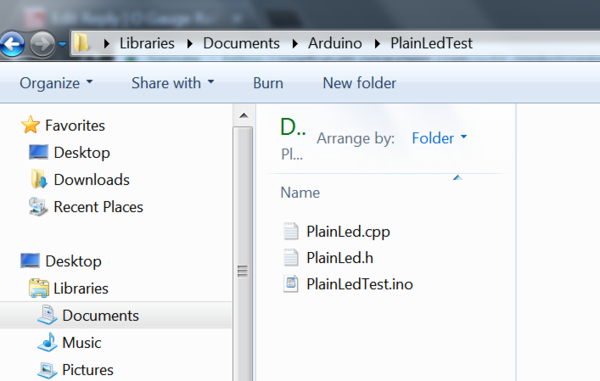
So now, we're ready to look at a test program for our "PlainLed" class. Before I began this exercise, I started by creating a NEW sketch in the Arduino IDE called "PlainLedTest". In your local file directory it will show up as a file with the extension ".ino" (identifies an Arduino sketch).
Each sketch created by the Arduino IDE will create a new file folder in the local directory. The "path" to that directory, on my Windows machine is Libraries - Documents - Arduino. There you will find all of the folders for your sketches. Here's what the "PlainLedTest" folder contains:
Manually moving files around in these directories is not advisable; I do it all the time. But use caution or you could lose all your work.
I've already written the test program which you can examine on your own. I suspect that the group of people who remain viewers of this thread are well versed in the language by now. However, if you need help with anything, I promise not to embarrass you or myself in any way. ![]() There are no bad questions. My email address should be available on my profile page.
There are no bad questions. My email address should be available on my profile page.
I will not attempt to cut and paste the test program here. It will be in the attachments below. However I will put up some pieces that will explain how it works.
The test phases include:
1. LED on for 2 seconds.
2. LED off for 2 seconds.
3. Toggle the LED on for 3 seconds.
4. Check that LED is on and toggle off, 3 seconds.
5. Check that LED is off and toggle on, 4 seconds.
6. Turn off LED, 4 seconds.
When all phases have been completed, the sequence repeats using the
next LED.
The test circuit includes 3 LEDs with current limiting resistors connected to pins 9, 10, and 11. These are PWM output pins which will be useful when we add fading capabilities later on. Here's a diagram:
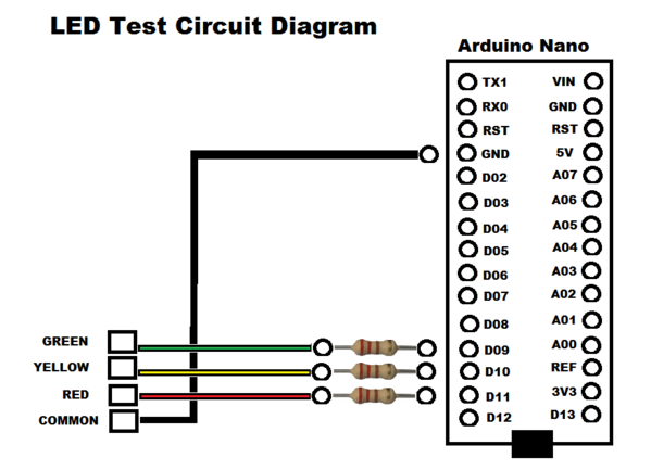
The LEDs are connected Anodes to the color connections and Cathodes all going to Common. You all know what the Nano looks like.

I've set it up on a breadboard with wires going to resistors and 2 sets of LEDs both green, yellow, and red. This test is run using the LEDs that I have mounted on an independent prototype board.
Our program demonstrates that turning an LED on and off can be way more complicated than that old blink program. But we have also seen the basics of building any type of class and creating any type of object.
Next time we will extend our PlainLed class to use the pulse width modulation capabilities of the Arduino to set the intensity of the LEDs. Can you say PulseLed?
-- Leo


