I believe I have made some progress since I first wrote the original post involving the O72 issues with the Atlas CZ cars and O72 switches. I appreciate the post replies and emails that offered suggestions and ideas. I have some conclusions that I have applied to my layout and cars. It is not perfect yet, but improved. I will share what I’ve have found to date, my actions taken and why. I found a variety of issues that varied from car to car. I think that these issues mostly appear when trying to use O72 curves and switches and probably become insignificant with larger radii.
1 Removal of air brake lines and steam pipes. Bending foot grab irons
The pipes hit the frame of the car, being one of the limitation of the truck rotation. They come off fairly easily, many of them are already off and in the box when you get them. The brake line comes off easily with the trucks still mounted but steam pipes need to have the coupler removed which means you also need the adjustable bracket removed. The steam line is more fragile than the break line and needs to be removed carefully. A miniature thin blade screw driver can be used to pry a little bit at a time on each side of the connection. It can be removed with out damage if done patiently and gradually. It is held in by a mortise on the coupler and tenon on the steam pipe. After removal of the pipes reassess whether the foot step grab iron interfere with the rotation of the truck. If they do, leave alone until you have finalized the height of the coupler, then if needed they can be bent up slightly with the needle nose pliers. This is much easier than reshaping or remaking new.
2 Centering spring stability
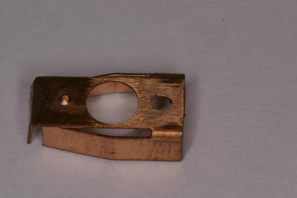
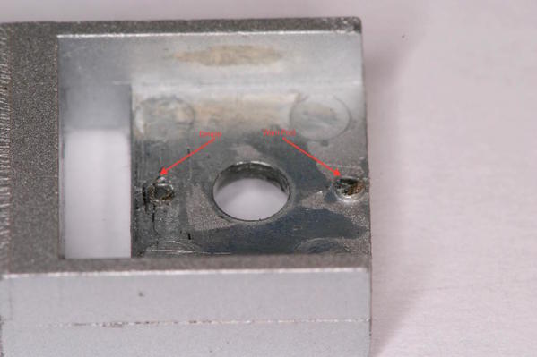
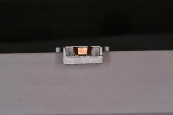
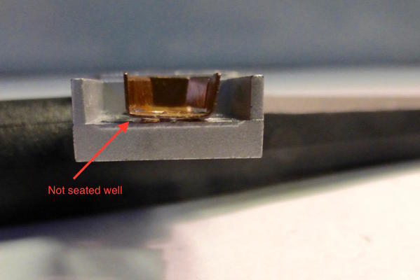
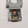
I found that on about 1/3 of my cars that the coupler centering spring was moving off the small dimple and post that is used to hold it in place. The spring is then resistant to re-centering the coupler after if moves off the post. It can be observed when exercising the coupler, that the spring will rotate. The spring can be stabilized sometimes by adjusting the tightness of the holding screw securing the coupler mounting (see #3). On the springs that couldn’t be stabilized with adjustment I used Mike’s CA Glue to hold it in place. Some of the posts showed wear. This is a very delicate procedure. No glue can remain on the surface of the spring that bears the coupler, the hole that acts as the bushing, or on the leaf springs. The leafs must be able to act as springs. I feel that if you are doing this you need to use scopes and head lights. I doubt that Atlas would approve this and might void your warranty
Box Spring
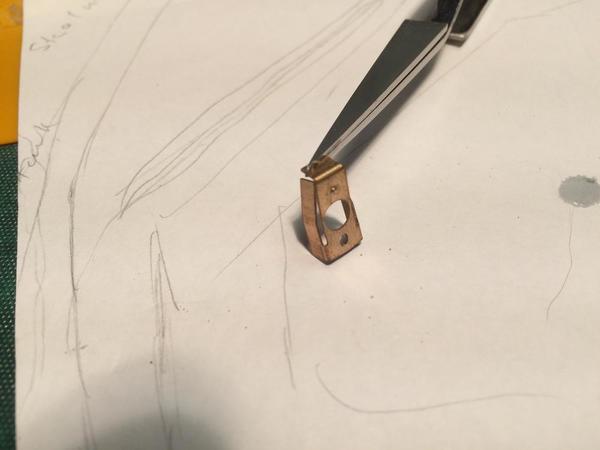
Post and Dimple Worn
Seated well and Glued
Seated well
Not seated well and will not work
3 Adjustment of coupler on the adjustable bar.
The cars I have, required that I adjusted the tightness of everyone of the attachment screw. About ½ were loose and dropping or were too tight to swing properly. If couplers are dropping they are also letting the spring become non-functional. It is a fine adjustment, similar to tightening a bearing or bushing on a car or bicycle wheel. My method was to remove the screw holding the release lever and then tighten the screw holding the coupler until it is fully seat and the coupler doesn’t swing. Then back off 1/8 to 1/4 turn. Check if it snaps back right and left and doesn’t have vertical slop. Most of my cars had a washer between the head and the adjustable bar, but a significant number didn’t have them. I believe the system is that the mounting screw is set then fixed when you tighten the screw that holds the coil spring and release lever. They should meet inside their common shaft although they are not the same gauge. You can over tighten the lever screw. I had 4 mounting screws that were bent. Two of which the heads twisted off when I tried to removed them. Initially I had thought they were bent from the thumb tack hitting parts of the switch, but I now believe it was from the manufacture over tightening the larger lever screw. I had also linked the bend I saw in the lever arm to the same cause (striking a switch part), but since most of the arms have a slight bend, I think it was from the hole punching process during manufacturing. I have set all of the coupler heights to ¾” + or - 1/32 from the top of the coupler knuckle to the top of the middle rail. The adjustment if needed is easily done with the 2 back mounting screw. Very few of the couplers needed this after tightening the coupler properly to the adjustment bar. If you need pictures or additional clarity with the adjustments, please email me.
4 Adjusting the rollers or the O72 Switch
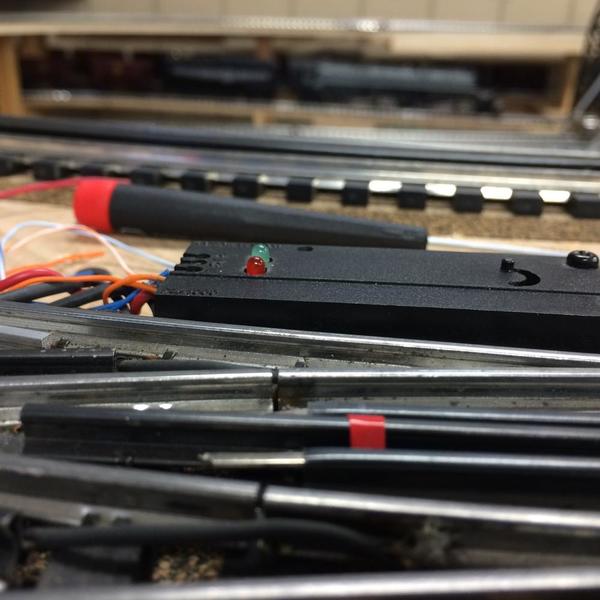
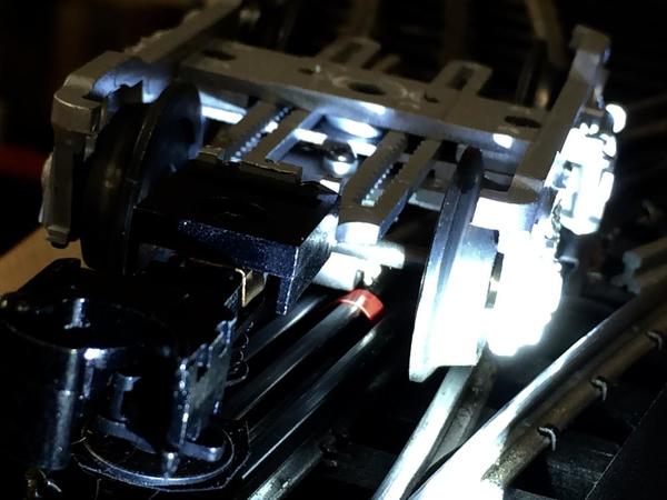
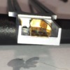
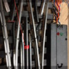
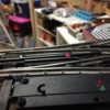
After all the adjustment were done, I still have significant derailing on the switches. The 21 CZ’s are extremely difficult to see what is happening when they go over a switch, but you can feel the binding some times with the right pressure on the car. I knew there is some problem between the truck and the switch. I took videos to help see the problem. I do not have any extra trucks but I do have extra cars. I removed the trucks form one of my cars. By doing so I could see the problem and cause, I believed. I can only say this is the cause on the Ross switches but I would think it would pertain to all the manufactures that have sharp rails versus tubular rails. My belief is that Atlas has used a roller that really has sharp edges (a true cylinder) compared to other rollers that have a chamfered edge like a salami shape. I have taken pictures I hope you can make out. The roller rolls in and drops down off the entrance center rail over the outside rail and onto another guard rail (which is lower) then needs to rise up to the exit center rail. The sharp edges prevent the roller from consistently rolling up on the exit center rail and when it doesn’t it causes a derailment. I believe the solution is to modify the roller or the switch. I will probably be doing both. The red tape on the switch picture is the area where the square edge roller hits the exiting middle (3rd) rail and binds. Without the body on the trucks it is very easy to see the problem, and make it reoccur in the testing. My solution is to regrind the edges of the rollers and place an elevating filler between the guard rail and the middle rail. The roller can be placed securely in a drill and the edges rounded by a fine file. I am concerned about removing and the replacing the roller and what affect it would have on the bracket. I do not know if Atlas would agree.
Sharp Edge Roller
Red Tape Contact Point of Sharp Roller
Red Tape Contact Point of Sharp Roller
Path of Roller Middle rail to outside rail to lower guard rail to higher exit middle rail.
Red tape and contact of leading edge of sharp roller causing derailment not allowing truck to follow track but forcing it to the right because it can't lift up to the rail
I will report back when that is done, the filler and grinding.
Thanks for following
Buzz


