Hello All - I finally have a little update on this project after being able to make some progress, focusing on getting the tender put together at this point. And as far as I know, it's complete as of tonight unless testing with the locomotive attached reveals the need to open it back up and troubleshoot anything.
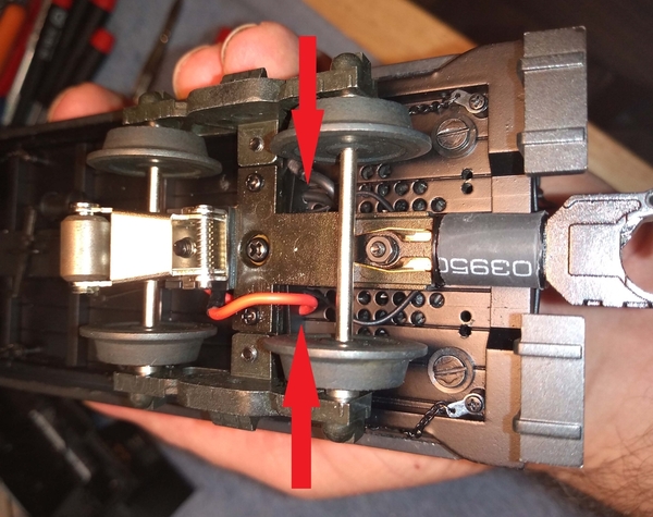
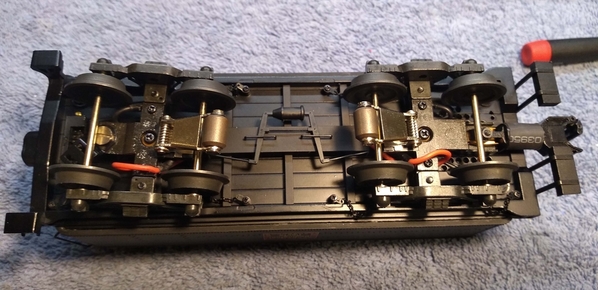
I mentioned previously I thought the trucks turned really stiff and couple be improved upon. The wires passed from the trucks through holes in the bottom of the tender in pretty close proximity which didn't give much room to flex, and the wire was pretty stiff to begin with. I finally received the little crimp style ring terminals (2.5mm and 3mm) I wanted so along with the high flex wire I ordered was able to assemble the new leads for the trucks. While tinkering with this I decided to re-route the way the wires went from the trucks into the holes in the bottom of the tender. Originally the wires from both trucks were attached such that they "pointed" toward the middle of the tender. What I especially didn't like was how the power leads from the pickup rollers were bent back flat on themselves towards the center of the trucks and then up into the holes in the bottom of the tender. I decided to do something similar to what was done with the wires from the rear coupler, which were sandwiched between the bottom of the tender and the tender frame, through small notches in the frame. As a note the bottom frame piece is removable with 4 screws that are visible once the trucks are detached. I added additional notches for the power and ground leads in the frame and routed the wires accordingly. The pictures below are the result... The trucks do seem to swivel a little more freely, and I like that this avoids any "pinched" bends in the wires.
Below is how the inside of the tender turned out with the new Cruise Commander all installed and wired in, along with the Railsounds board and new speaker / enclosure. The speaker is just attached with hot glue since that was the most straightforward.
You can't see it in the picture, but the Railsounds board is mounted on two spacers about 1/8" thick on both ends leaving an open gap beneath in the center. This is where the leads from rear truck and coupler come up through the bottom of the tender, coming out toward the Cruise Commander board. The two switches under the water hatch that were retained are the Run / Program switch and the smoke On / Off switch. For the moment I've retained the original light on the tender, but did replace the original "orange" looking LED with a warm white Evans LED. The leads from the front truck come up through the bottom of the tender about in the middle of the Cruise Commander board. To keep them from touching contacting the board I did install a little upside down "U" channel to bring the wires out to the side of the board.
I junked the original header connector at the front of the tender with a Digikey SBH21-NBPN-D07-RA-BK (https://www.digikey.com/short/8pd0qn84) . What I liked about this is that it had the pins bent at 90° on the inside. The original was just a straight connector with the wires bent over sharply to clear the bottom of the tender deck. The connector slides into a bracket that holds it in place in the tender, which you can see attached with the two little brass screws. With a little sanding on both ends of the new connector it fit nicely into this original bracket so I was able to reuse it. Though this is a 14 pin connector patterned after the original, I'm only using the outside pins - 4 on the right side, and 5 on the left, leaving the center pins unused. Based on a little tinkering I did before, leaving the center pins empty will reduce the interference where the drawbar attaches to the front truck.
My only regret is that I couldn't quite figure out how to squeeze in either a 9V battery or the "Your Last Battery" equivalent, so I hope that won't end up being a significant issue. I don't suppose anyone knows if there's an ultra compact alternative to either of these out there that I'm not aware of?
When it was all back together I put the tender on the track for just a quick test... I was able to program it to the desired engine ID number, hear the sounds (except the chuffs of course), open the rear coupler, and turn on the rear headlight when put in reverse.
Now the fun will begin with trying to squeeze everything into the engine itself! Looking back I want to thank Mainliner for attaching his picture of the "as built" internal wiring of the engine... That helps me remember how some of the wires were routed in that rats nest since this has turned into somewhat of a long term project!


