RayR posted:… Can you amplify on the operating concept you offered? What is the control board, where is it obtained? Can we collaborate on a more detailed wiring scheme?
See if these "talking points" help. This applies to 1 signal head controlling the track voltage to the preceding block. Multiply accordingly based on the number of blocks (in your case 4x or 5x per loop):
[a] As I understand it, you're going to use Atlas signaling hardware. I do not know exactly what that is so I'd need to see wiring diagrams or the like to show you how to integrate it with block voltage control. For example, presumably there are 4-wires going to each signal head. 1 wire is common, and 1-wire each for R, Y, and G. I'd need to know what voltages are involved; LED, bulb, DC, AC, etc.
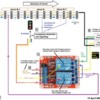
[b] The "operating concept" is to take the Atlas signal wires going to the signal head and additionally route them to the control (relay) board as shown. Presumably you have 2 track voltage transformers. One is set to the full speed voltage, the other is set to the reduced speed voltage. The relay board has 2 relays. When a relay is ON, COM connects to NO. When a relay is OFF, COM connects to NC.
If the yellow signal is "ON" then the upper relay turns ON. If the red signal is "ON" then the lower relay turns ON. If you follow the logic, the relay module will apply FULL track voltage when the signal is Green, REDUCED track voltage when the signal is Yellow, and no track voltage when the signal is Red.
I believe early on you said you envision two transformers - one with the FULL voltage and a second with the REDUCED voltage. Another method that has been discussed in several OGR threads is to use a single transformer with the FULL voltage...and then use diodes to lower the FULL voltage by several Volts to become the reduced voltage. This discussion can be deferred.
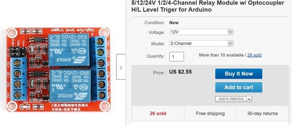
[c] The relay module is widely available (eBay, Amazon, elsewhere). If you don't mind waiting a few weeks for free shipping from Asia, a 2-relay module goes for $1-2 per relay. These come in 1,2,4,8 and even 16 relay modules which can reduce wiring if using multiple pairs. For example, a typical eBay listing might look like:
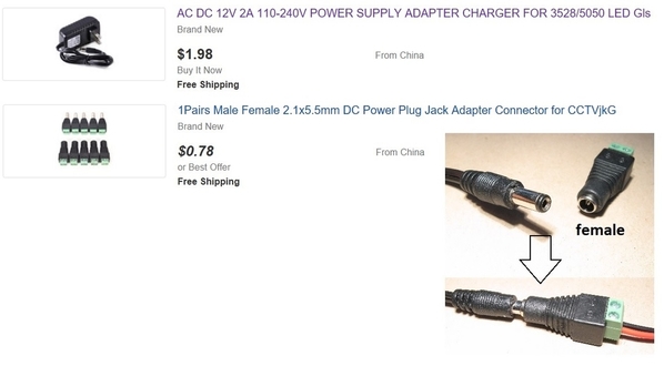
[d] The relay modules I'm thinking of require a DC power supply. In this case I'm showing 12V DC relays so you'd need a 12V DC power source; this is typically done with a DC-output wall-wart...widely available or about $2-3 on eBay (free shipping from Asia). One adapter as shown below could power dozens of relays.
If no DC power is applied to the relay module, then both relays will be OFF and this is equivalent to a Green signal so Full voltage is applied all all blocks. This is useful because you can then have a single toggle switch that powers all the relay modules in a loop. By turning OFF all the relay modules you are effectively disabling block control...and the FULL track voltage is applied to the entire loop. The signaling will still work; this mode might be useful when moving consists to and from the yard or between loops using the throttle handle assigned to FULL voltage (when in automatic).
----
Well, hopefully this sheds more light on the matter. It is a lot to take in.
As an aside, I'm thinking I'm re-inventing the wheel here! I know lots of guys use Atlas signaling and surely someone (or Atlas themselves?) has mated signaling to block control...though perhaps not using these attractively-priced eBay relay modules.


