


Norm Odsather posted:Hey GunrunnerJohn, man I need some help!
I'm not sure if I'm doing something wrong that just cost me 2 Super Chuffer cards or if I got 2 bad cards when I ordered them. I wired in the first one, went over my wiring against the diagram multiple times because this is my first go at something like this. I put power to the test track. The Cruise Commander and RailSounds came up like they were supposed to. I saw the Chuff Generator LED lit up. Put a little throttle to it and nothing from the Super Chuffer and I noticed the headlight LED was not lit. I powered down, checked my wiring again. Powered it up again and no LED on the Chuff Generator and nothing from the Super Chuffer. Just a heated smoke element. After checking I found no power from the 5v circuit and the headlight LED was blown by a 10v output from the headlight out circuit. Checked the diagram and that was the only LED not shown with a resistor. I assumed because of the rule 17 that the board handled that. So I installed a resistor on the headlight LED and tried the second card I had. Again the LED worked on the Chuff Generator but nothing from the Super Chuffer then the 5v circuit went away on that card too. But at least the headlight LED didn't blow as the resistor saved it. It did light up, but at full intensity. I powered it all down and did a walk away and do something else before I blew a gasket... Later I went to check the voltage going to the headlight but when I put power to the test track something popped on the Super Chuffer. I've been through my wiring over and over checking against the diagram and I'm at a loss. All the Cruise Commander and RailSounds are still working fine. What ever popped on the Super Chuffer and let its magic smoke out didn't spike the TMCC and sound. Any ideas? I'm about ready to scrap the Super Chuffer and Chuff Generator idea and just run the smoke unit off a constant voltage power source and use the reed switch for the sound.
Every board is visually inspected and then 100% function tested on a test set before it's packaged. The headlight circuit specifically goes directly to a single white LED on the test set, if it were cooking them, I'd be the first to know.
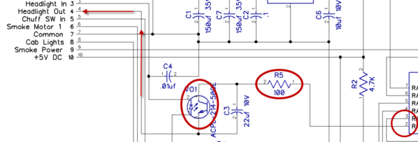
There really is absolutely no way that you get 10V on the LED headlight output without some bad wiring. Here's the circuit on the Super-Chuffer that drives that LED. It goes from the microprocessor port through a 100 ohm resistor, an opto-switch, and to the headlight out circuit. Nowhere is there a possibility of getting in excess of 5V on the line as that's the voltage from the microprocessor. There is no resistor required, it really is handled internally. The headlight has been working this way for the life of the product, and I've never gotten any reports of problems with the LED. I've personally wired at least 50-60 Super-Chuffers in installations without any of these issues.
I never say never. That being the case, anything can happen, and I could conceive of some failure on a single board, but a failure of two in a row is a bridge too far, at least IMO.
In your case Norm, I can't begin to know how things are wired or what is going wrong without seeing it. I'm really sorry you're experiencing issues, but without a lot more information, I can't really suggest what might be going on. In the isolated cases that folks have cooked a Super-Chuffer (yes it's happened a couple of times), the suspect wiring was fairly quickly isolated. If you want to send those back, I can examine them and possibly tell you where the excess voltage is coming in. Sadly, if the headlight circuit is getting sufficient voltage to blow LED's, it's likely that the excess voltage is getting to the microprocessor and blowing things. OTOH, it is a socketed part, so it's "possible" to revive them.

