


Guys, we are a little sidetracked from my original question. Assume the following, conventional setup with modern ZW-L. Running postwar with some new Legacy/visionline engines. My initial drawing shows generally what I'm up to. So, I will install either the Airpax breakers Steve seems to like...
https://www.onlinecomponents.c...00aobv-10090638.html
or the...
PSX1, GRJohn seems to like... Have ya'll come to consensus which is "better" for our model train application? I do not have the knowledge base to pick one. And, the PSX, when it trips, how do I reset it? On the airpax, why 5amp? shouldn't I want a 7.5 or 10 amp?
Moving to the TVS... zooming in on one of my loops... excuse primitive drawing...
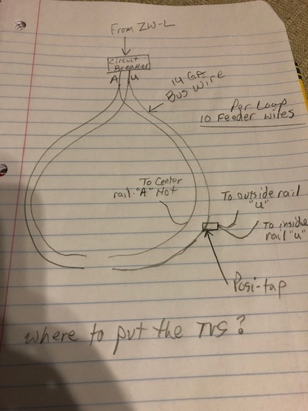
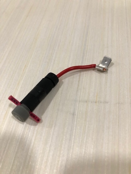
The system I'm going with (see my test mock up) uses Post-tap connectors to tap into my 14ga bus, 16ga coming out to a crimp on spade. Actually, based on what I've been reading I'll probably have 2 16ga wires coming out of the tap to have one to outside and one to inside rail. (Gargraves/Ross). I read this is preferred over just one to the outside.
Using this system, where do you suggest I wire in the TVS? Every feeder? I have 2 independent double-loops. So that's going to be like 40 feeders I think.
I was not planning to use the black terminal strips, and don't care to if possible.
I would be most grateful for constructive instruction/comment on point.
thank you for sharing your knowledge.


