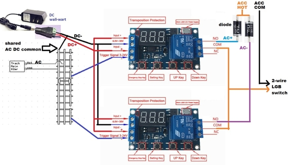
OK - if the LGB 2-wire switch uses the 2-diode (half-wave) method for polarity:
Shown above is a ~$3 timer relay module configured in a so-called non-retriggerable "Delay OFF" mode.** Upon trigger the relay turns ON, then there's a settable delay (in your case 0.5 to 1.0 sec per your comment), then relay turns OFF. Non-retriggerable means the trigger can remain active during or after the relay operation but the relay turns ON only once for the chosen time interval.
If this looks like a direction you'd like to pursue, I'll provide more details as I still have this timer module set up on a test track for a different OGR thread. I can even make a video showing it in action.
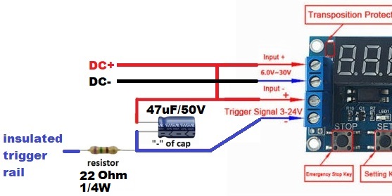
There is an additional issue of intermittent/noisy triggering when a consist enters or leaves the insulated rail section. When there is only 1 or just a few axles straddling the outer rails, you can get multiple triggers rather than just one long-continuous "clean" trigger. It should be benign in your application. In other words you may get multiple 0.5-1.0 sec pulses of power to the LGB switch when a consist enters or leaves but they would be in the "same" direction if that makes sense. If this is an issue, you can install a 10-cent resistor-capacitor trigger filter which I've detailed in many previous OGR threads using these low-cost relay modules.
** Addendum. Here's a snippet (spelling / grammar errors included!) from the timer module instruction sheet showing its different modes. Mode P1.1 is what you want for non-retriggerable operation.
Operation mode:
P1: After triggered signal, power relay on time OP, then turn off; within the OP period following operation:
1) P1.1: signal being triggered again is not effective
2) P1.2: signal being triggered again, start time again
3) P1.3: signal being triggered again, reset; disconnect relay, stop timing
P2: giving the trigger signal, the time after shutdown relay CL power relay OP time; then timing, turn off the relay
P3.1: give the trigger signal after the power relay on time OP, CL shutdown time relay; then operating cycle above cycle gaive signal again, shutdown relay stop timing; cycle times (LOP) can be set
P3.2: after connecting. no need to trigger signal, power relay on time OP, CL shutdown time relay; then the operating cycle above timea cycle (LOP) can be set
Q4: keeping the function of the signal; if there is no trigger signal, the time will be canceled, relay stay connected; when the signal disappears, timing OP turn off the relay; over time, if no signal again, the time is cleared


