I'd like to see your schematic before commenting. For example, I'm not clear on why you need a "quad" comparator implying 4 comparators for something like this. What are you comparing?
If you're saying there are 2 bulbs - one indicating the switch is "straight" and the other indicating the switch is "diverge" then here's another idea:
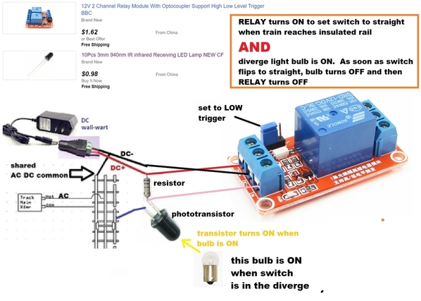
The idea here is you no longer need a timer to limit the power applied to the solenoid to 1/2 sec, 1 sec or whatever. You only power the solenoid if the switch is in the "wrong" position as indicated by the red or green bulb. In the example above, the phototransistor turns ON when a train enters the insulated rail section that demands the switch be in the straight setting AND the bulb indicates the diverge position. If the switch is ALREADY in the straight position, then the bulb will be OFF and the relay will not fire.
There are many schemes that use this kind of feedback that stumble for this reason. Sometime the switch get jammed or stuck in some mid-position (between diverge and straight). Because the switch is in no-man's land, the indicator may be simply wrong and the red or green bulbs might even be BOTH on, BOTH off. Of course if the switch is mechanically jammed then even the timer method would not work so one can argue this is a moot point.
I show just one direction (one relay) but you can buy a 2-channel 12V DC relay module for less than $1 per channel as suggest above. A phototransistor is essentially an electrical switch that turns ON when light is presented. A resistor is a penny or two. So if indeed you have lamp indicators showing which position the switch is in, then for about $2-3 you can eliminate the timers and save a few bucks.


