Some of this is coming back now as it has been a number of years since i did this installation.
My objective back then was to retain dual control, that is leave the MTH controller in place but also to have it operate through the AIU off my handheld. It still exists that way but is now redundant to the way I run my trains and all the manual controllers, transformers are no longer insight. I just use my handheld.
So the reason for the two diodes was to replicate the diodes that are in the controller to prevent control feedback when reversing the can motor to go UP or DOWN.
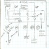
Here are the diagrams. Not too good for scanning in but maybe I can take you through it.
THIS IS THE WHOLE SCHEMATIC
THIS IS WHAT IS IN THE CONTROLLER AND HOW LAND PATTERNS ARE CONNECTED.
THIS IS THE BOARD IN THE TOWER AND HOW THE LAND PATERNS CONNECT TO THE OPERATING PARTS.
THIS SHOWS THE AIU ACC PORTS 7 thru 10 AND HOW THE GROUND FROM THE CONTROLLER IS FED INTO THE in OF THE RELAY. YOU CAN SEE ACC 7 GOES STRAIGHT TO THE BUCKET MAGNET. ACC 10 GOES STRAIGHT TO THE SOLENOID DROP.
HOWEVER PORTS 8 &9 OUTPUTS have diodes that are tied together and controls the different directions of the can motor.
This is a better picture showing how controller wiring and AIU wiring are spliced together.
Good Luck!
Hugh


