


Doctor: There are also the DZ 2500 switch motors, which are TMCC controlled, but you already have an AIU. Best wishes with your project.
There is a lot of information on the Atlas 6924 relay since it was introduces. A recent post related to installation, the board is cheaper than the DZ switch and relay. IMO, not your average model railroad electrical item.
Recent post on how complex the relay boards can be. They do work and work well, if properly installed per the Atlas diagrams. Note that track circuit fuse protection, power routing, was added after the 6924 boards were introduced.
(Previous post on another thread.)
InputA and InputB The two short pieces near the frog of the switch are wired via Green and Red wires to InA and InB on the board.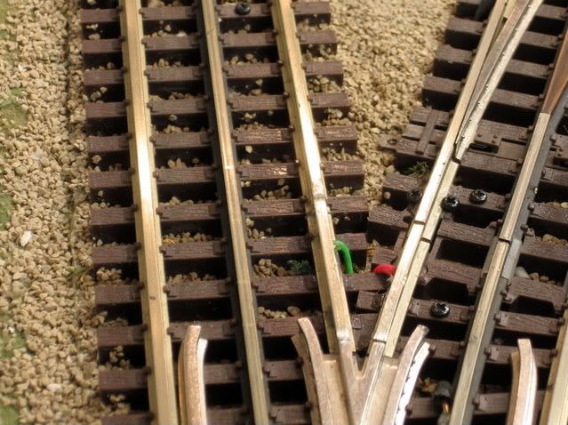
There are two (dead rail sections) on each switch, one straight and one curved)
It requires (3) wires to power these sections, (logically) via the relay. Note the wire attached to one of the dead rail sections.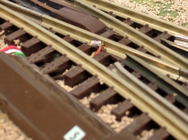
From the 6924 relay board to the switch motor requires (3) wires. Accessory common, Through (Out A) and Out (Out B).
Total wires required Relay board and accessory common to the switch.
(1.) InA Electric non-derail function. Input rail to relay board and/or push buttons/ or ASC controller.
(2.) InB Electric non-derail function. Input rail to relay board and/or push buttons/ or ASC controller.
(3.) Out A Relay board to switch motor terminal.
(4.) Out B Relay board to switch motor terminal.
(5.) Accessory Common Accessory common near the 6924 relay board to the switch
motor.
Add Power Routing.
(6.) Track power from the switch location back to the relay board.
(7.) Dead rail power Through from the relay board to the appropriate dead rail.
(8.) Dead rail power Out from the relay board to the appropriate dead rail.
Add Power Routing (using two track circuits COM1 and COM2). (Two switches)
(9.) Track power from the switch location back to the relay board
(10.) Dead rail power Through switch position to the appropriate dead rail.
(11.) Dead rail power Out switch position to the appropriate dead rail.
(12.) 6924 board power daisy chained between boards. (2) wires if daisy chained.
(13.) 6924 board power common daisy chained between boards. (2 wires if daisy chained).
Total of (8 or 11) wires between the 6924 relay board and the switch location.
Wiring for the 6931 dwarf lights can be done with the 6931 dwarf light board supplied as part of the dwarf lights. Connection requires power to the board and connection to the through and out terminals of the switch motor.
Depends on whether you are into the wiring part of the hobby. IMO ![]()
![]()
