SketchUp is like learning to play guitar. You can learn some simple stuff in a couple of weeks. To play like Jimmy Page you're going to need years if even that's possible. My greatest difficulty with SketchUp is on more organic shapes. In its native state it's really an architectural program. It's not a true skinning program like Mesh Mixer and Blender are. It can do that, but you need a raft of plug-ins (many of which I have) and even then, my results are less than satisfactory. The 3D Warehouse is, indeed, a good starting point, but you have to carefully analyze the drawing for those solids and reversed faces. Also, as I've noted before, the folks who draw them don't always follow good SU rules in keeping everything down to the lowest level in groups and components.
As to your question: The usual answer is "that depends". For example, it could very easily print a nice 0'scale bench grinder or vise, plus a raft of hand tools, but the vise handle would have to be two to three times thicker than scale to have it last through the clean up stage. If you didn't have to trim a forest of supports off the model, the chances of fine detail survival is improved, but the supports are a necessary part of the process. I'm working on ways to use diamond burrs to abrade the supports off fine details with some success. Even then, I'm broken off tiny stuff just by picking up the model improperly. And don't drop them on the floor! Experience… ugh!
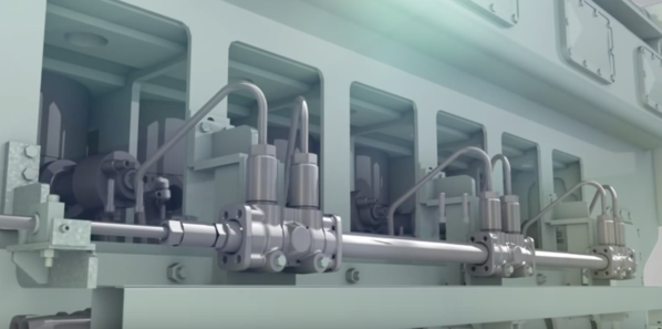
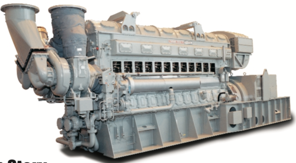
I've just downloaded images of a Fairbanks Morse opposed piston diesel to model. The FM engine has its primary injector pumps on the outside of the engine with an exposed cam shaft driving it. The HP fuel line then feeds through a rectangular opening in the engine's side to the injector nozzle assembly that penetrates into the cylinder's center. I'm sure that the printer would render the injector pumps and shafts very well, and it would attempt to do the fuel line. But they would be really delicate. It would also render the interior of those compartments, but again, it will depend on the support layout as to whether it would be practical. Notice also that the metal thickness of those compartments look only to be 3/8" to 1/2" in real world. That would be very thin printed. I would have to thicken them up a bit to ensure they would be viable. I'm thinking that I should write an instruction set on using SketchUp for 3D printing.
Unlike the EMD, I did find a good elevation drawing of this engine and a listing of the critical dimensions. It should be an easier thing to model. That is except for that induction system with those massive turbo chargers. This engine has a big Roots style blower on the one end and turbos on the other. Serious efficiency. I think they're still manufacturing these engines for power generation. They were more successful in marine and stationary use than in locomotives. They were not as easy to repair on the road.
I don't have any FM powered engines. I guess I'll need to get myself a Trainmaster...
Keep asking questions and I'll keep answering.


