I may put an article together on making the bumpers. I think that would fit well with OGRR's projects.
All the bumpers are finished, touched up, and fastened to the shelves. I drilled two clearance holes on an angle pointing towards the bumper front and used some #2 self-taping screws to fasten the bumper to the shelf AFTER I liberally applied some Aleens. The screws are really only holding the bumper down until the glue dries. Once that happens you'd have to destroy them to get them off. Good!
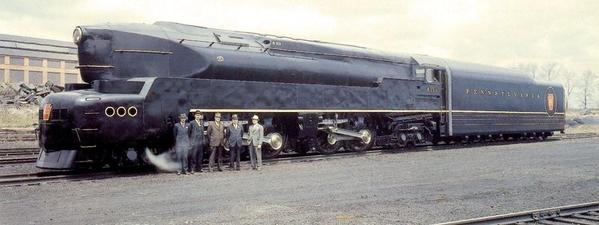
I also started cleaning off my disgusting work bench. I didn't completely clean it... no need to go that far, but I cleared enough space to put my engine support stand and finish working on my T-1. This is my favorite engine. It is number 6100, which is the first prototype of Pennsy's T-1 4-4-4-4 duplex series. The engine is fully streamlined by Raymond Lowey (also designer of Studebaker Avanti), and was one of two demo units. 6110 had an added booster on the trailing truck. Here it is on its delivery day from Baldwin Locomotive. My uncle worked at Baldwin at that time. That engine is BIG! Notice too how closely coupled engine and tender are. There was a diaphragm that was less than foot across. Couldn't use that engine on tight curves! Also the rigid frame 4-4-4-4 actually had a fixed wheelbase of a 4-10-4, not a 4-8-4 and this was with 80 inch drivers. More reason for large curves.

Here's my engine. 3rd Rail did a splendid job on this engine, especially in the disconnected handrails, and they weren't shiny.
The engine was running awfully. It was stumbling and stalling, even on track that was cleaned, so it was time for a tune-up. The wheels and rollers were filthy, and one traction tire was torn. I thought I had traction tires for it, but couldn't find them so I contacted 3rd Rail and they sent me replacements. THANK YOU 3RD RAIL!\
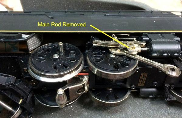
The traction tires are on the last driver so they're not blocked by cross heads, but that doesn't mean it's an easy job. The main rod needs to be completely removed so it's out of the way. The side rod needs to be removed too.
Luckily, there's enough play in the that side rod so you can bend it up to get over the crank pin. It was touch and go, but it did clear. If not, either the rod would have to be removed on both ends (as it would on the real engine) or the bottom plate would have to be removed and the entire driver axle taken out. As you can see in the pic, the screw for the front part of the side road was completely blocked by the crosshead guide. The drivers would have to be rotated to bring that pin clear.
The brake shoes and hangers must also be removed to give clearance entirely around the rim to put on the traction tire. Using a small flat-bladed screw driver I was able to manhandle the tire into position. The first side took a while, the second one went much faster. Ahhh... the beauty of the learning curve.
I then finished cleaning the wheels with Xylene and re-lubricated all the moving parts. On the track the engine ran perfectly.
I also sanded all the repaired crossing and added a coat of joint compound to the last remaining one. Tomorrow that will be dry enough to sand so I'll be able to touch up and paint all the remaining white areas.


