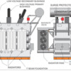
Really great stuff Lee! In my research I had found many of the details you included, but still learned more. The Xfrmer I'm building is probably too big for a distribution station, but I'm going with it anyway. You're right about the bus system, but I'm going to simplify it a bit. I noticed in your course you didn't talk about lightening protection. It seems that a lot of the details around the substation are lightening related.
Today Number 1 grandson was here so besides working on the transformer, we put the first coat of paint on his F-22 kit and I worked with him to perfect his ability to use an air brush. It's coming out as a nice model and he's been working on it, on and off, for as long as I've been building the railroad.
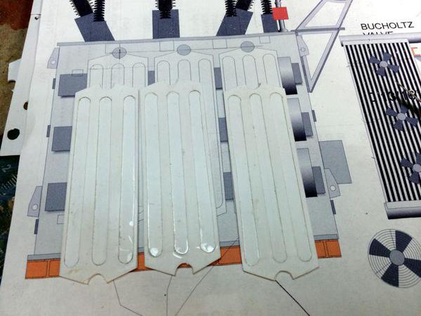
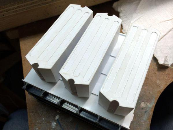
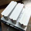
I finished the radiator "boxes". I now have to figure out how to best simulate the actual cooling fin portion. It's been a nice scratch-building sub-project that had its own challenges.
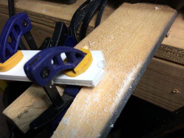
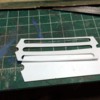
I shaped one end plate by first locating the position of the oil manifold's 1/4" holes. I pilot drilled them and then used my battery DeWalt to drill the hole in the 0.040" styrene since I could control the speed very carefully. Then I trimmed the angle cuts at the ends. It looked right so I needed five more. Grandson suggested stacking them and cutting them at once. He's a good problem solver. I have to admit that I already figured that out, but gave him credit for a good idea.
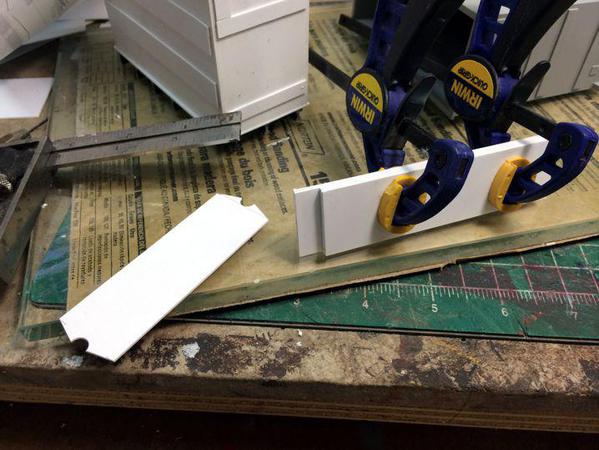
Again I drilled the holes first and then trimmed the ends using a razor saw over my bench hook.
The ends had tapered a bit so I did a touch up job on the belt sander. With styrene you have to sand very gently since you'd end up melting more than sanding if you lean into it too much.
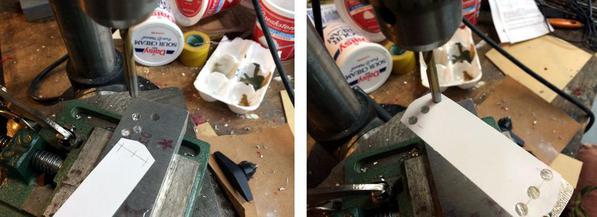
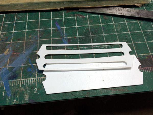
The front ends of the radiators get a overlay that adds some interest to the assembly. I'm using thin, 0.010" styrene for this. I tried to drill it, but regardless of how I turned the drill, it chewed the heck out of it and was a total fiasco. I realized I had to punch the holes. A #6 drill was the diameter of the end curves so I did one of my jerry-rigged, poor-man's punch scheme. For punching soft materials this method works pretty well.
It goes like this. First grind the back end of the drill to a punch shape. In this case I held the drill at 45º to the corner of the grinding wheel to impart a v-shaped cut to the drill's end. I grind until the newly ground surface extends to the entire edge of the drill.
I then take the drill to the drill press and using the "normal" end, drill a hole in some convenient piece of metal. Since I was punching styrene it didn't matter that I used aluminum. The workpiece should be clamped securely to the machine's table.
Now, take the drill out and insert it upside down into the chuck. Don't tighten it yet. Since you're trying to tighten it about the flutes, the drill isn't actually round and will clamp at any any and will not re-enter the die hole that you cut. So to ensure that the drill will re-enter the die, let the drill drop into the hole and bring the chuck down until the drill bottoms out in the chuck. While holding everything in this position, tighten the drill in the chuck and the punch is ready.
The only thing I would do differently if I were to do this again would be to get a bit more sophisticated in how I positioned the work piece under the punch. In this case I just eyeballed the punch over a couple of cross hairs. It needed a fence where I could actually keep the holes on each end aligned.
To complete the detail I just carefully cut the material between the holes and cleaned it up with a half-round file.
This overlay was attached to the end cap with liquid cement with the touch-n-flow.
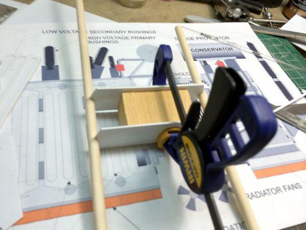
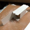
I didn't want to waste too much material making these radiators. They don't need much structural strength so I used a wood block cut on the chop saw to the inside dimension to hold the end caps apart. After carefully positioning the end caps onto the block using a 1/4" dowel to align the oil manifold mounting holes, I glued it all together with thin CA and accelerator.
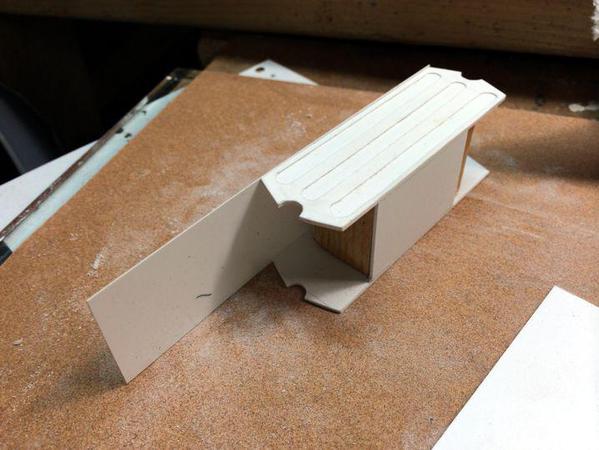
I was skinning this with 0.010" which is very flimsy, so I added some cross members flush with the end caps. I then glued the thin sheet to the sides. The first piece I left the end really long thinking I'll just trim later, but I quickly found out that the angled ends made cutting it more difficult. From then on I pre-trimmed the skin close to final length and trimmed the remaining 1/32" with a razor blade.
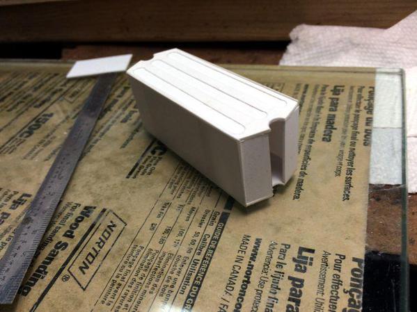
With the skins on I measured and cut each top piece so it was a snug fit between the end caps. This step was a bit finicky and took some time and many scrapped pieces.
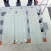
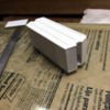
After the glue dried I took a sanding stick and filed all the edges so it looks like a real full-size assembly. By the end of the work session, I had all three radiators housings finished waiting for the detailing on the two ends that are actually going to be visible.
I'm thinking that I'm going to fabricate the radiator fins by carefully alternating thin pieces of styrene standing on their ends and then their sides. I'll also have to made a standoff to support the fans.
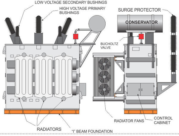
Just as a refresher, here's the plans I drew for the transformer.


