Well... today was fruitful. I've got a lot of images to share so bear with me.
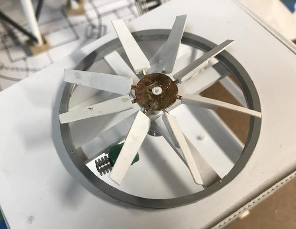
I printed out the drawing I made of the fan and decided on a mixed-media approach with a brass hub and connectors and styrene blades. I had thought about making the hub thicker using a piece of the 5/8" pipe that I used for the flare, but I none of it left. I was going to drill the arm holes around the perimeter. Instead, I laid out a brass hub with 8 equally spaced lines where the arms will go. I drilled the #31 hole before cutting out the disc.
Cut it out with a jewelers saw and slightly missed on one line, but it doesn't matter in this instance. Dressed up the edges with the belt sander and then needle file.
I soldered the 8 arms onto the disk with the RSU. Again, this soldering job would have been ridiculous with a standard iron, but was a piece of cake with the RSU. I had to use heat sinks to keep other pieces from de-soldering since they were so close together and the disk had a lot of mass.
I soldered opposite sides so the heating wouldn't be too bad. At the start I used hemostats, but went to using heavy steel angle and v-blocks. I added some liquid rosin flux to help it along. I realize now that I could have used different temp solders which also reduces de-soldering, but this worked okay. Here's a pic showing the RSU's tweezers in the act.
After cleaning up the excess flux with alcohol I trimmed all the arms to a specific length. Later I trimmed them even shorter.
I applied a thin layer of spray glue onto my fan drawing and stuck it to a piece of styrene. I cut out all 8 blades from 0.020" sheet. After cutting I soaked the blades in Goo Gone to remove the patterns and then in alcohol to remove the Goo Gone. The blades were too thin to drill the holes for arm attachment, so I needed to add some stock to their backs. After this dried I shaped it a bit some it's not visible when looking down at the fan.
I used the small carbide drill to put in a starter hole and then opened it with a #53 drill to match the fan arms. This is the back side.
After installing all the blades and adjusting their pitch I added a drop of thin CA to the joint and they were done.
I added a NBW casting on the hub to dress that up.
While the fan blade blocking was drying I added some Evergreen 1/2 round stock to the top edge of the venturi. This note only finished the edge, but also helped stiffen this thin plastic part. When it dried, I sanded the top edge some the thin stock coincided with the beading.
The last piece the fan needed was the trash screen. Ideally, it would be a circular screen that would have to be photo etched. Since I can't do that (yet) I decided to use the Bridal tulle I bought last week. I used the larger gauge (chain link fence) held in place with two ABS rings. In this case, I used the MicroMark pressure sensitive adhesive (PSA) to hold the tulle to the rings. I made the lower ring a smaller size than the upper.
I trimmed the excess with a fresh, sharp #11 blade. After test fitting into the space, I realized it needed some stops to hold it in position. It took a couple of tries to get the height just right.
Here's the screen test fit in place. Starting to look pretty spiffy. I didn't glue it in since the fan needs to be painted. This will keep workers from being maimed if they fall into the fan housing. Safety first!
I cut the lower portion fan shaft to a length for the lower pulley. I cut it too short since the motor extends a little farther into the unit. I'm therefore thinking of changing from a belt drive to an angle drive (as Marley uses on the prototype). This should be an easy piece to cobble together.
Tomorrow I'm going to get the railings into place, and put the bracing on the box's outside. And then I'll build the water baffles which aren't vertical. They slope forward and are not flush with the front at their bottoms. These are going to be black so it's another reason why the roof will not be glued until after assembly and painting is finished.
My roll of 22 gauge red/black zip cord came today to make wiring up all these LEDs easier. I bought a 100 ft. roll. I also received the flashing white and red LEDs that I can use for aircraft warning lights on the flare tower (and others), and I got the K-S 3 foot lengths of brass tubing for the light poles and making the chain link fencing. Instead of using steel rod as Brennen included, I'm using small brass tubing. It will be easier to shape the cross-lap joints and much, much easier to solder securely. It all has to be painted anyway so whether it's brass or steel, it doesn't matter.


