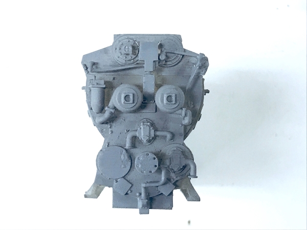
Thanks for the tips. I did apply solder directly to the wire and, yes, it did remove the insulation. Another multi-task day. With all these punch list items, I find myself jumping from one thing to another. I had to concentrate. The Gantry is effectively finished except for a load to hang on the hook and some decaling showing the tonnage capacity. I'm out of decal film and will have to get some. I finally printed a complete 567 front end with all the parts where they should be, but ended up with a back end lacking a flywheel and broke off the oil lines from the blower's bottom. One of these days, I will get all the parts done correctly and create a perfect engine. That being said, I put the first on on some cribbing and stuck it into the engine house just for effect. From handling I did manage to break some more parts on this very delicate part. I'm going to get some flexible resin and mix it with the one I'm using to impart some impact strength to the parts.
I glued that first generator on the back end and put it on some Ross railway ties. In this view you can really see those gaps at the buttresses bases. I may have to fill them if I'm going to continue to shoot these neat interior shots.
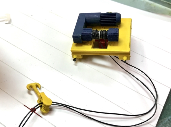
I painted the new hoist carriage, and then wound the string (cable) around the drum. I used the DeWalt as my power turner since I could run it real slow. I just CA'd the string to the drum and started winding. I would have liked the coil to be a little more regular, but it's buried in the top of the building and is not visible. AMS… When winding was done, I thin CA'd the spool with the threads hanging vertically down. I knew which way done was since the bottom face of the drum is un-ribbed.
I threaded the line through the hook and positioned it at the height I wanted and left it long. This was more challenging than it looks since there is that sheave guard complicating things. I had to prepare the tiny mounts that were grown on the carriage base. They were concave and needed to be flat so I filled them with some Bondic and using a diamond burr to flatten them. Most of the strength is the CA'd joint with the gear box.
To set the hook height, I took the free ends and wrapped them around the traverse motor's drive shafts. I had put some eyes in this new part, but they were way too small and kind of fell apart. I put the carriage in my Panavise and hung some serious weight on the hook to tighten it all up. The hemostat wasn't enough, so I added a V-block.
When it was where I wanted it, I added glue to the sheaves and to the string wrapped around the drive shafts and then clipped the excess.
I epoxied the carriage onto the gantry. Before doing that I painted the little details on the gantry. I put the gantry into the building and took some more pics. I want to hang a generator on the hook. BTW: I think I may have found out why I'm getting such sporadic engine operation in the engine house. It's those darn filler pieces. I think there are places where they rise up higher than the center rail and cut off power at the pickup rollers. I may end up removing them altogether and unballasting the track to simulate tracks laid on concrete like you see in big train stations.
To facilitate the hanging, I finally grew a generator with the shackles. Unfortunately, they're really fine and one is cracked already. I may be able to fix that with Bondic. You can even see the eye in the "removable" shackle pin. The printer will resolve it. Whether or not the part will sustain itself is another question. I set this part reversed from how I print the others. I had them with the hollow end facing down so the uncured resin would drain out when I put them out of the Machine, but this put the supports all over the end with the bolt detail and around those delicate ribs. This time the supports were on the flat back end and under the support brackets. It was much easier to clean up.
Right now the Machine is producing some of the those machines that failed earlier and some other stuff too. I went back and looked at all those drawings again last night. This time I set SketchUp's reverse face color to lime green. All of sudden there were lime green spots all over the place. No wonder that metal band saw was falling apart when I first did it. It's one thing to learn how to run the machine. Most videos you see talk about that. It's another thing to understand about the 3D drawing requirements. It's not sufficient for the object to be a solid. All the faces must face outward. ALL OF THEM! The SU drawing doesn't care about which face is visible. If all depends which direct you push pull the object into three dimensions. It's like putting on your socks. You can pull them on right side out, or inside out. It's the same in SU. If you pull it in one direction the outside sides will be visible. If you push it the other way, the inside faces will be visible. This is especially true when pulling a circle into a cylinder. What makes it so insidious is when it's just a little ring of reversed faces that are at the hub of a handwheel. The wheel falls off since there's nothing holding it. I'll know tomorrow how successful I am.
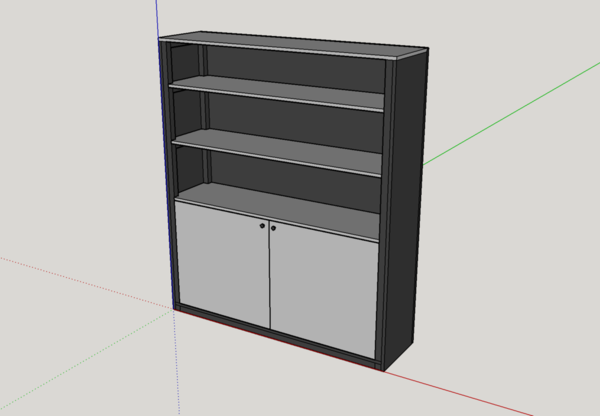
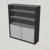
Here's an example of what the model looks like coming directly from the SU 3D Warehouse. In color it looks terrific. But when I turn off the color and highlight the reverse faces, this is what you get and it wouldn't print worth a darn.
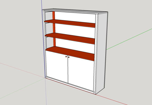
The surfaces in red are reversed and will be invisible to the SLT Translator.
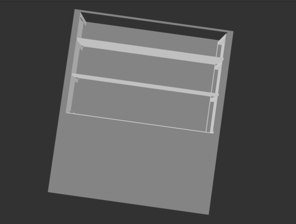
And here's what the SLT file looks like. This is what goes to the slicing software. What the SLT doesn't see, the slicer doesn't either. In this image, the roof is missing entirely, and the shelves are just a single plane. Planes have zero thickness and therefore can't exist in the real world. The back members wouldn't print either. When I draw things from scratch I manage the face direction from the get go and don't have too much editing to fix them.
The last thing I did was get one working light completed. I revised my test rig to include the LED driver just to be safe. I tested the lights unwired, wired, and then in the fixture and finally with the base attached. All worked. They're slick! The heads are still that translucent resin so they're glowing. I hope I'm able to put enough paint on them to make them appear solid. There will be on over each overhead door, the side door and the machine shop door.
I soldered one more, but didn't get the base on. So that's 2 down and 3 to go. I also glued on all the doors. I have to fix the roofing on the machine shop. It's unwrapping.
Like I said… multi-tasking.


