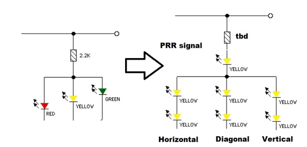
stan2004 posted:Of the 3 options, I'd go with #2 if you are going to make an OSH Park (or whatever) PCB design. Circuit #1 is limited by the drive capability of the LM339. If you are driving more than one signal head in parallel, or if using high-power LEDs (100 mA instead of 20 mA nominal operating current), or even miniature incandescent bulbs then you're out of luck. Circuit #3 depends on the different in drive voltage for different color LEDs. This works of course of the Red-Yellow-Green LEDs but what about incandescent bulbs or a PRR style 7-LED signal head which uses all the same color LEDs?
Did you guys actually prototype circuit #2? I think the "OR" circuit which turns off the Green LED when Red OR Yellow is on is skating on thin ice.
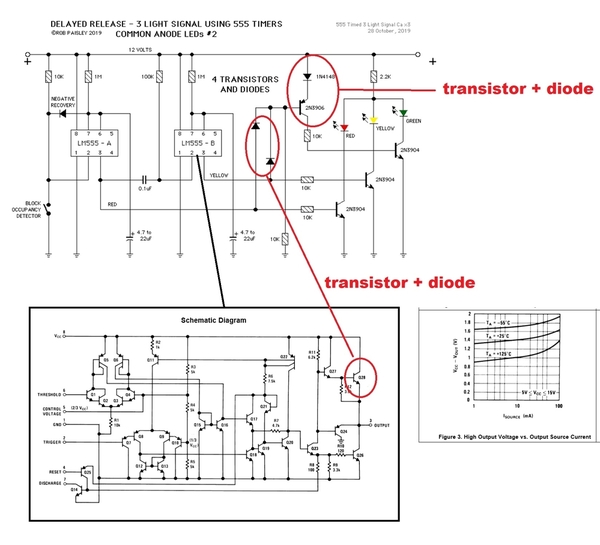
The Yellow and Red LEDs are turned on when one or the other 555 chip is ON (at pin 3 output). This ON signal does NOT go to the positive supply voltage because there's an output transistor as shown in the 555 internal schematic above. As the curve shows on the right, the "ON" voltage might be about 1V below the DC+ supply voltage. Then each Yellow/Red output goes thru a diode which further lowers the voltage.
So this transistor + diode voltage drop now tries to turn off the 2N3906. While a diode appears to have been added above the 2N3906, it's not clear to me that either the Yellow or Red output generates a high enough voltage to turn OFF the 2N3906.
Good point you make Stan, think you nailed it. I was breadboarding this crcuit over the last day or two. While it does seem to work fine, I noticed that when either the red or yellow leds are lit, the green is VERY dimly lit. I did not even notice it until I turned the shop lights mostly off. I think it might be noticeable though if you were running trains in subdued lighting.
Then I tried the 3 x 555 circuit that Rob (Circuitous) has also published. It seems to work quite well, and there is no false triggered green lighting at all. I had to drop the base drive resistor on the green led 3904 to 2.2K to get full ma to the led, but good after that.
All consiidered though I am leaning towards our relatively simple circuit R5.4 published earlier in this thread. It works quite well, has the option of a voltage reg, can be triggered by an independent opto circuit, and with fewer components the board size is smaller, not to mention less expensive. Just waiting for my board order to arrive so aas to do a test build and make sure all goes as planned. ![]()
Rod


