


Well, I did the reverse engineering I mentioned. Here is a longish post:
It is possible to modify a non-ESU smoke unit so that it connects to the LokSound L or XL decoders just as an ESU smoke unit does by connecting the smoke unit to the specialized ESU smoke unit terminals: HTR+/-, MOT+/-, and TMP+/-. This capability allows you to take direct advantage of all the LokSound capabilities provided for ESU smoke units. The missing component in some smoke units is a Negative Temperature Coefficient (NTC) thermistor.
What started me down this road was a “deadrail” conversion of a Sunset 3rd Rail Big Boy (3-rail, “Late Version”) originally outfitted with TMCC and a nice Lionel smoke unit with dual output (photo below).
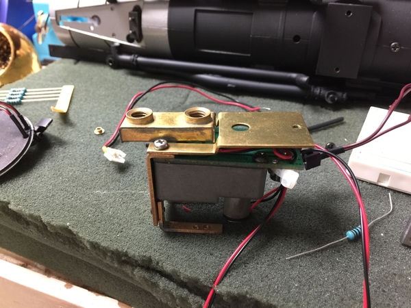
I wanted to retain this beauty and use a LokSound L V4.0 decoder that is controlled by an Airwire CONVRTR-60. THOR73’s posts inspired me to work through using this smoke unit with the LokSound L V4.0 decoder. I thought that if I could figure out how the ESU smoke units created their “temperature” inputs to the LokSound decoder, then I could retrofit the Lionel smoke unit so that it would be “input compatible” with an ESU smoke unit. This retrofit turned out to be simple.
I reverse-engineered an ESU 54678 smoke unit by measuring the resistance between the heater resistor leads (HTR+/-): ~23 ohms; motor leads (MOT+/-): ~16 ohms; and thermistor leads (TMP+/-): ~100K ohm at room temperature. Each of these components is electrically-isolated from the others. When powered by a 14.8V LiPo battery, the LokSound L V4.0 decoder I had on hand produced the following results on the ESU Profi board using the LokProgrammer (with ground measured at the Profi board's ground terminal):
Terminal | Smoke off | Smoke on (Throttle=10) |
HTR+ (not connected to heater resistor*) | 13.4V | 13.2V |
HTR- | Open | Switched open/ground @500Hz ~30% duty-cycle PWM |
Fan+ | 0V | Pulsed <= 5V (difficult to determine with low Frequency chuffs) |
Fan- | 0V | 0V |
TMP+ | 5.1V | 5.1V |
TMP- | 1.3V | 3.7V |
* Battery+ (14.2V) connected to heater resistor + input |
|
|
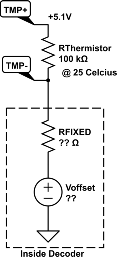
The difference in TMP- between unheated and heated conditions suggests, but does not prove, that the thermistor’s decrease in resistance with increased temperature is manifested by a voltage increase at TMP- as part of a voltage divider where the thermistor is in series with a fixed resistor resident in the decoder, possibly with a low-side voltage offset:
So right off the bat, the ESU smoke unit’s heater resistance (23 ohms) is similar to Lionel’s (27 ohms), and both smoke units use 5V fan motors. The Lionel was missing only the thermistor. Lower resistance smoke units (around 8 ohms) might be problematic to convert unless retrofitted with a heater resistor in the 20 ohm neighborhood or use an externally-supplied, lower HTR+ voltage. The heater and fan motor similarity between the ESU and Lionel smoke units seemed to make this particular Lionel smoke unit an excellent surrogate candidate.
Thermistors with 100K ohm resistance at 25 Celsius are commonly-available, usually with a “B” parameter of around 3900 Kelvin. You can Google what this parameter means (simplified Steinhart-Hart Equation: R(T in Kelvin)=R@TRef*(exp(B/T-B/TRef)) ). While I was not able to verify that the ESU smoke unit used precisely this type of thermistor, testing described later supports this selection.
The photo below is the Lionel 27 ohm smoke unit PCB, part #610-PCB1-045, Rev C (Lionel replacement part #691PCB1045), that was retrofitted with an “axial,” glass-coated 100K NTC thermistor with a B of 3892 Kelvin. (Well, it’s actually a Lionel replacement PCB since I cut some traces retrofitting on the original PCB that I regret doing. Interestingly, the original PCB did not have the mangled lettering of the replacement PCB that some like GUNRUNNERJOHN have noted.)
The 3-pin power plug on the PCB can be used to power the heater resistor since the outputs from the rectifier/5V converter on the PCB do not connect to anything after removing the fan motor plug. The ground on the PCB MUST be isolated from the heater unit metal case since the PCB’s “ground” wire will be connected to the LokSound L’s HTR- terminal that regulates the heating resistor’s current path to ground! Electrical measurements revealed good electrical isolation of the metal case from the heating element.
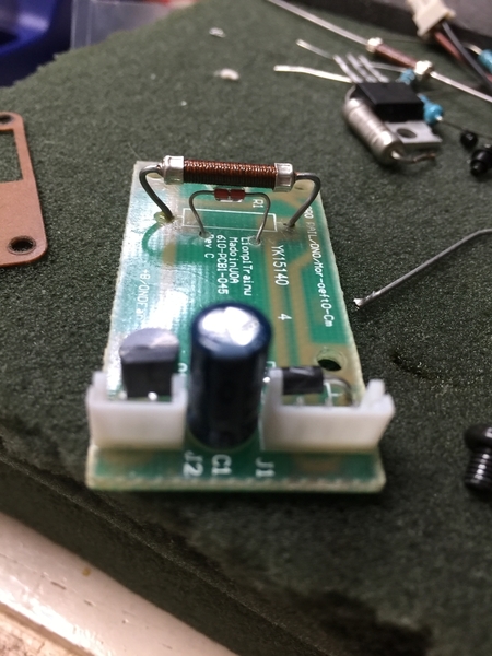
Two holes were drilled in the smoke unit’s PCB board, and the thermistor was inserted and soldered to two wire leads that connect to the LokSound L’s TMP+/- terminals. High melting-point solder was used in the off chance that conventional solder might melt at the high operating temperatures of the heater resistor and thermistor (max around 250 Celsius according to documentation for the ESU smoke unit).
The two heater wires from the three-pin PCB plug connect to the LokSound L’s HTR+/- terminals. (Pins 1 and 3 are shorted together on the PCB and connect to one side of the heater resistor. Pin 2 is ground and connects to the other side of the heater resistor.)
The motor wires directly connect to the MOT+/- terminals. Out of sheer luck, when the red motor lead from the smoke unit is connected to MOT+, and it’s black lead to MOT-, the fan motor spins in the “correct” direction.
As GUNRUNNERJOHN has suggested, I also replaced the original 27 ohm ceramic resistor with a Lionel 27 ohm replacement #6008141055.
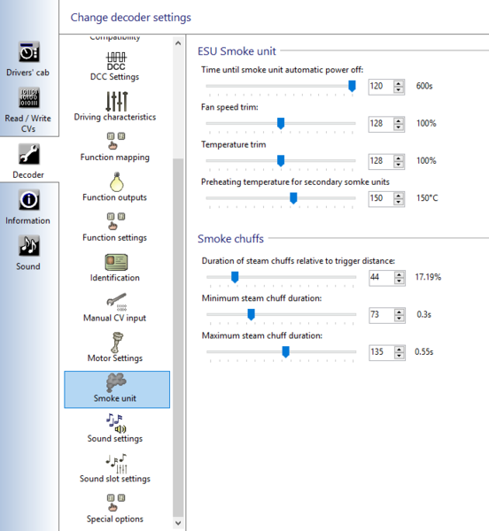
Once the smoke unit’s six outputs were connected to the LokSound L’s ESU smoke unit terminals, there were some modifications needed in the ESU sound files and decoder set-up, since they did not originally activate the ESU smoke unit. First, follow THOR73’s directions regarding the connection between sound and smoke chuffing under the “Smoke unit” menu. Note especially that the smoke unit’s automatic power-off time should be reset since the default is 0 seconds. I don’t know if 0 means never turn off, but a non-zero setting seemed like a good idea to me.
What differs from THOR73’s discussion is the sound-file set-up for an ESU smoke unit. Editing the sound files reveals that most “nodes” have an option to set the “ESU Smoke Unit” parameters. Frequently these settings are turned off, but there are some useful “presets” you can select and experiment with. An especially interesting preset is the “preheating” preset that is available in the stopped state.
Mute State:
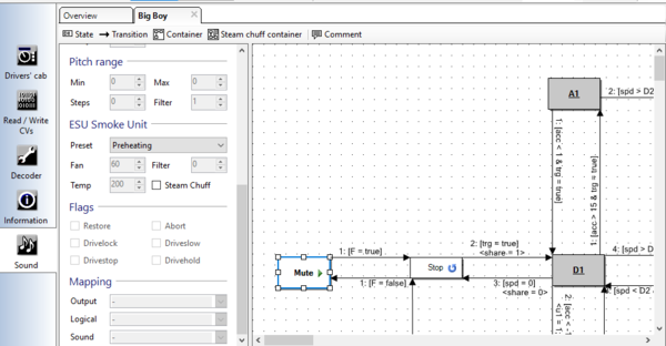
Here are the other states I modified, but I am by no means expert or knowledgeable about these settings. Usually, I chose a “Preset” and then selected the “Steam Chuff” checkbox, which preserves the parameters of the preset (unless you change them), but turns off the Preset name.
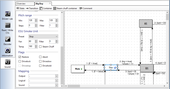
Stop State:
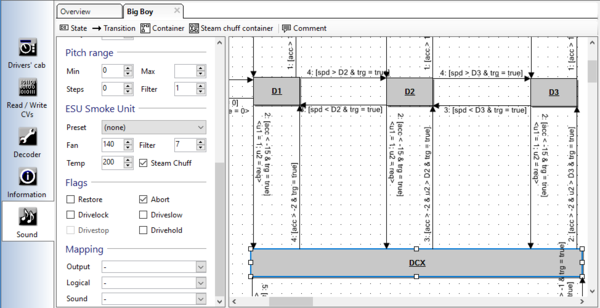
DCX State:
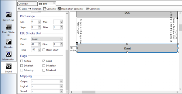
Coast State:
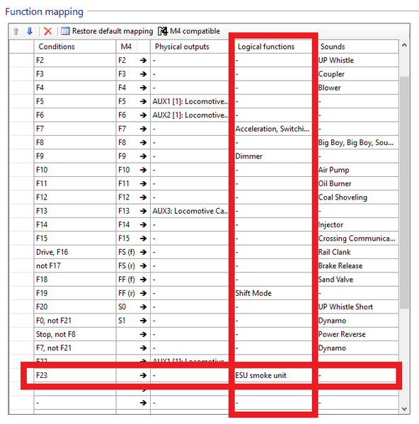
After editing these sound nodes, the next step is to set an “F#” to turn the smoke unit on/off on the “Function mappings” menu. The “logical” outputs column provides an “ESU Smoke Unit” selection, so I selected F23 as the ESU Smoke Unit on/off toggle.
A TESTING WARNING: The ESU 53900 Profi Decoder Tester does not appear able to provide adequate power to either an actual ESU Smoke Unit or surrogates described here! In actual operation, the LokSound L is perfectly capable of providing sufficient power, but the Profi board is, in my experience (or inexperience), NOT able to do so. I initially thought the culprit was the puny AC to DC converter provided to power the Proof board, but power connection to a very hefty 14.8V LiPo battery did not solve the problem. The workaround is to use either THOR73’s high-side MOSFET switch mentioned in this thread or use the low-side MOSFET switch described in the same thread. Either way, you will need to take power (about +14V DC) from the source providing power to the Profi board and use the Profi board’s HTR- output to control the MOSFET switch that will, in turn, control the smoke unit’s heater. If using THOR73’s high-side switch, then you connect the smoke heater as he describes. If using the low-side switch I presented, the smoke unit’s HTR- connects to the switch control input, and the switch’s ground connects to power ground.
Reiterating, THIS SPECIALIZED MOSFET SWITCH IS ONLY NEEDED FOR TESTING WITH THE Profi BOARD! In actual operation, the LokSound L is designed to adequately power an ESU smoke unit by direct connection to the decoder’s ESU smoke unit terminals, as is the modified smoke unit described here.
Here's the "proof in the pudding" video:
Please forgive the disassembled state. I haven’t finished the deadrail conversion, but this video does demonstrate battery power with the LokSound L V4.0 controlled by an Airwire CONVRTR-60 wireless receiver.


