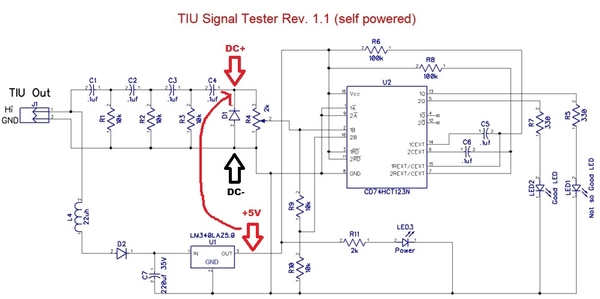
stan2004 posted:Here's one minimalist approach to "calibration" - no scope, no battery, no other components required! This uses the relatively accurate on-board 5V voltage as a reference.
With the 2 LED method (vs. original 1 LED method), there are 3 "zones". (1) BOTH LEDs blink meaning good signal level, (2) 1 LED blinks meaning marginal/degraded signal, (3) Neither LED blinks meaning very low or no signal.
1. Apply AC track voltage to module. Presumably the "Power" LED turns on. Use DC voltmeter to confirm you have 5.0V DC at the point indicated. The DC- side of the DC measurement is the circuit ground.
2. By momentarily touching +5V to the DC+ point as shown (using, say, an alligator jumper cable), you are effectively applying a 5V trigger. By turning the trimpot fully in one direction, you should be able to make BOTH LEDs flash each time you tap +5V to the DC+ point. By turning the trimpot fully in the other direction, you should not be able to make either LED flash. The idea is to adjust the trimpot to the case where you're at the threshold between NEITHER LED flashing and 1 LED flashing. To be clear, this is a separate threshold than between 1 LED flashing and BOTH LEDs flashing.
This simple (?) procedure "calibrates" the unit to flash both LEDs on a 10V DCS signal. This is probably good enough IMO but to each his own.
3. If you have access to a "known good" TIU channel, it will surely trigger BOTH LEDs as it appears you get more than a 10V DCS signal. You can then further adjust the trimpot with the "known good" TIU knowing that you have AT LEAST a 10V output. To do this, you then send a real DCS signal out the TIU and adjust the trimpot to the point where 1 LED flashes and BOTH LEDs flash.
bump for calibration technique post


