If you're game for some minor mods:
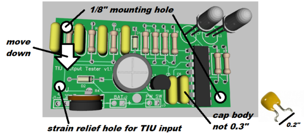
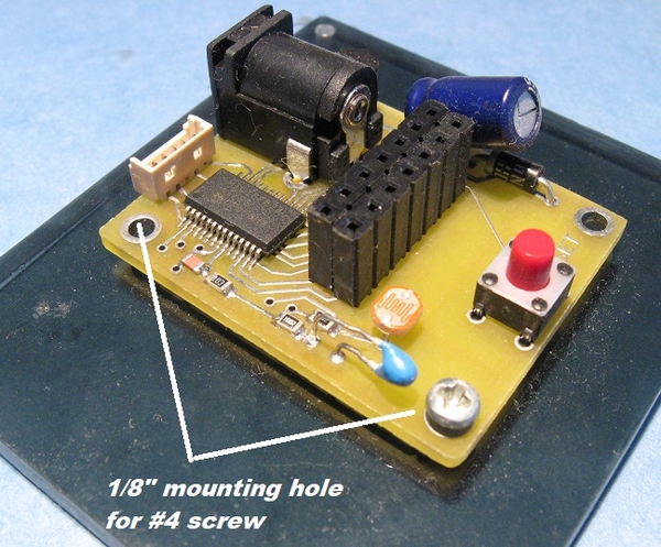
Without increasing board size, I think you could add 1/8" mounting holes in diagonal corners as shown. This would take #4 screws. I like to mount tiny boards like this on a piece of acrylic so the nothing shorts out on the bottom of the board. Example:
I'm not sure what everyone's plan is for connecting the TIU input wires, but perhaps a strain-relief hole is needed for those two wires too.
I think the components in the upper left can be moved down to make room for the mounting hole. I note that your 3-D cap body looks much larger than the actual 0.2" lead-spacing component...where the leads are actually bent out to make them wider. Point being there is more room available than the component outline suggests.
It looks like the 3-D rendering of the LEDs shows the flat-side on the left while the silkscreen shows the flat side on the right. Trivial but for whatever reason caught my eye right away!
I'm not sure on what the call the 2 LEDs (weak, good, whatever). But note that for a "good" signal, both L1 and L2 should blink. For a "weak" signal, only L1 will blink. The trigger voltage to the #1 half of the 123 chip gets the larger trigger voltage. The schematic calls L1 "good" and L2 "weak".


