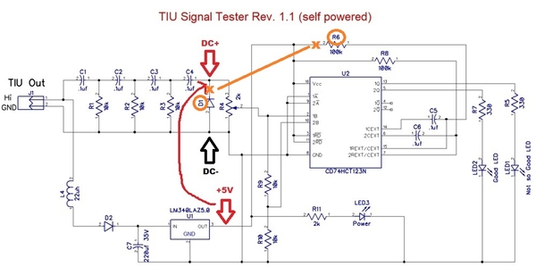
For those that don't have an oscilloscope, here's a video showing the calibration method I suggested earlier using the on-board 5V DC voltage as a reference level:
As it turns out, you can simply short the wire-leads from two adjacent components (D1 and R6). Or as engineer-joe suggested, you could attach a momentary SPST push-button switch to these points if the circuit is mounted in a box whereby you don't have access.
Note I added a drop of white paint to the trim-pot to better show the adjustment angle.
This sets the threshold to about 10V. You can then further refine/trim the threshold to a known-good TIU output. Note that turning the trim-pot CW increases the threshold. The idea is without a starting point (10V in this case), you don't know if your "known-good" TIU output is at the desired 12V (or whatever) signal level. As Adrian previously reported, you can get all 10's on the DCS signal test with a signal level of less than 5V; but a TIU port that only puts out 5V is probably damaged.
Again, thanks to rtr12 for putting together these kits!


