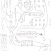
OK, I did some bench testing with the Gateman accessory. You can try this on yours at your own risk. You have to be careful with DC in a solenoid,there is much less resistance and voltage needs to be reduced to a minimum to avoid overheating. Hooked to the buck converter,it pulls out reliably at 8.2 VDC and stays out until voltage is reduced to 2.2 VDC. I left it on a the 2 volt setting for an hour with seemingly no ill effects while Mr Coyote stayed out. So ideally when the train enters the block the accessory will get 8.2 volts for a few seconds,then voltage is reduced to 2 volts to keep it activated without overheating. To do this I will use 2 relays, 2 capacitors and some diodes. Here is a schematic hooked to a ZW. When a train enters the block,the train wheels complete the circuit and relay one coil is energized.The left set of contacts on relay one discharges a 2200uf 35 volt capacitor into relay 2 coil,energizing it for about 2 seconds. Initially both relays come on, then relay 2 drops out. The other contact sets are configured so that the accessory gets 8.2 volts DC from the buck converter,then it is reduced to 2.2 volts until the train leaves the block. Voltage drop is provided by 9 diodes in series. Relay 2 bypasses the diode string. Click on photo to enlarge
So I made up the board. I have other accessories also to activate. 2 highway flashers,a Lionel scale crossing gate, and a warning bell. To accomplish this I made up a 4PDT relay out of 2 DPDT ones,(2, 12VDC coils wired in series.)
Here is a shot of the block and the other accessories that need to be activated when a train crosses the block.
So in addition to the Gateman circuit,other items are added. The first 2 relay contact sets are for the gateman as well as the relay to the right of it. The middle blue item is an interval timer which shuts off the warning bell after a set time. Otherwise it would be annoying. To the right of that is the buck converter to supply power to the gateman. and the diode dropping string,mounted on a barrier strip for adjustable taps. I used 3 amp ones but one amp ones would be sufficient. To the right of that is a flasher timer,set at about 2 seconds to flash the highway signal bulbs. The American Flyer ones have been altered to flash. A forth set of contacts on the block relay will switch the scale crossing gate. I bench tested the board and will install later.
As I move along the layout,I will make up additional boards required for the accessories.
That is my progress so far,I need to do a bit of wiring as I have a few accessories,then I need to do the block system and random automated station stop circuits.
Dale H


