Thanks all for the kind encouragement. To clear things up a bit, I don’t have plans to produce this as a kit. I use the term “kit” in the context of the prototype Erie Railroad - they purchased the pre-cut steel sheets and structural components (kit), and welded it together at their shops. It was their design, they just outsourced the cutting of the steel - I’ve outsourced mine to a robotic laser.
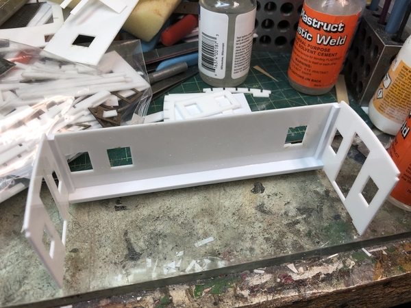
Glue - Gluing the .060 styrene that I am using to itself, is almost as hard as hand cutting the material. They make a liquid adhesive that does the trick, except that it evaporates almost instantly so you have to use a needle applicator, and a bigger problem, it’s so nasty that it would probably kill the five brain cells I have left. The only liquid model glue that I’ve come across that says it will work with acrylic on the label is Plastruct Plastic Weld (the orange bottles not the white). Which is good, since it’s the cement I’ve enjoyed using for years. Most liquid glues are formulated for styrene to styrene bonds, however, because Plastruct products come in styrene, ABC, Butyrate, and acrylic, they had to make something that could bond these to each other. It’s still a bit sketchy bonding acrylic to acrylic. If I was working with thicker material it would be easier, ie more surface area at glue joint. With .060, you need to hold things steady for a bit while the glue works, however, using styrene square rods as a backer in the corner makes for a quick, solid joint. The following photo shows the square rods - 0.125x.0.125 in corners and 0.125x0.312 along the bottom of the walls. The bigger piece is used to make attaching the undercarriage with screws easy.
The notches on the ends by roof are for another styrene rectangular shape. The roof was welded to the body with this caboose, so there isn’t the typical slight overhang, but rather a slightly rounded edge. My idea, and it might not work, is to glue the roof sheathing to the upper rectangular block and then round over slightly with sanding pads. The whole assembly there will be easy to sand styrene.
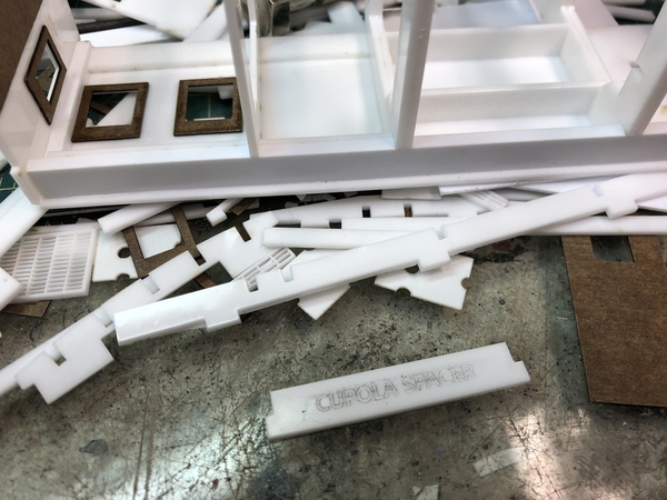
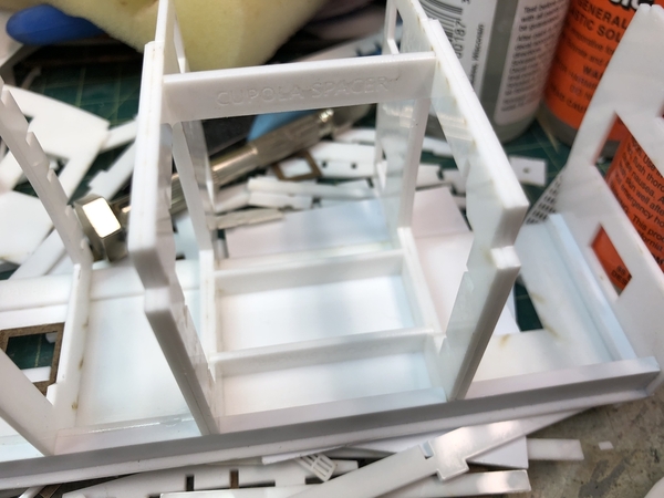
Adding the intermediate supports and cupola ends. I might have overkilled this, again, since acrylic is very rigid and stable, but it can’t hurt I guess. On the long side of cupola I have two frames - one against the cupola side and one just behind the double windows. There is another frame against the opposite cupola side. The ends get an abbreviated frame, due to lack of space with windows and doors along roof line (yet to be added) All frames were notched for the roof joists and the styrene block along bottom edge by the laser. All parts were also labeled by the laser. On both of the experimental assemblies I installed one of the cupola sides facing the wrong way. The outsides have weld lines around the window frames that need to face out, so I added labels on this version. At bottom of photo is one of the spacers for the cupola sides, two of which are visible in upper right portion of photo. There are also more simple, rectangular spacers on the longs side visible above and below the windows. These spacers are to make everything self-aligning, and self-squaring. There is very little that needs to be visually aligned while gluing. It makes for fast construction. Right now my estimate is about two hours of less start to finish, except for details like steps, handrails, etc.
Spacers more visible in the above photo. Note the labeling.
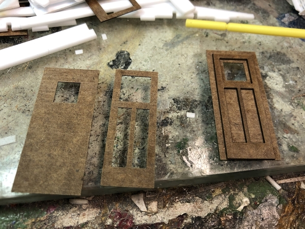
Windows and doors are cut from poly-backer, also called laser-board in some circles. Poly-backer is around 0.020 thick. The thinnest acrylic I can get is .060. The laser will cut styrene, but it’s too soft and the edges aren’t crisp. The doors are just a two part assembly using ACC glue. The poly-backer adheres great to the acrylic with ACC also.
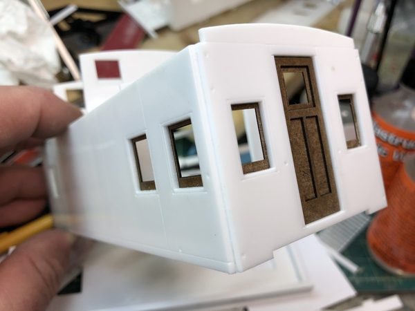
I’ll leave you with the partially assembled body. It’s easier to add the windows and doors as I go along. Note the weld-lines around the windows, and on the sides, pretty close to prototype locations. Obviously, more of a scribe than a weld, but if you were really nuts, you could glue a small styrene rod to the grooves to better simulate a weld line. The corner is stepped intentionally for a .060 styrene quarter round rod (Plastruct #90893) The prototype had rounded corners. Also note the pre-drilled holes for all the grab irons. That’s it for tonight.
Jim


