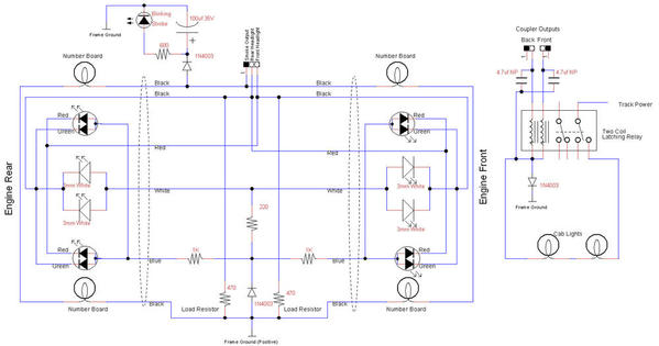
Well, yes! That was the most important part! For ERR boards, I use a standard LED, diode, and a 470 ohm resistor for a single LED. If I have two headlights, I put them in series and use a 330 ohm resistor and diode, or in parallel with a 220 ohm resistor and diode. Remember that the frame is positive when driving LED's from the TMCC R2(4)LC. Here's a wiring diagram from my BEEP upgrade where I directional markers and headlights. I also had lighted number boards, separately controlled strobe, and separately controlled cab lights. This is a bit "fancier" than you might be considering, but it shows how the markers were wired. One point, ignore the load resistors, they were the "old" way of doing the triac loads, I've since moved to using the capacitors on plain TMCC or the ERR Cruise Commander Lite. The other ERR products have the load capacitors and don't need any additional components.
OGR Forum Supporting Membership Required
Access to this requires an OGR Forum Supporting Membership
OGR Forum Supporting Membership

Help support this forum with an OGR Forum Supporting Membership.
You will be able to watch the videos in the INSTRUCTIONAL VIDEO FORUM!
A one-year OGR Forum Supporting Membership is only $12 per year, so sign up now!
OR
Access the ALL the OGR VIDEO FORUMS AND over 300 back issues of OGR
with a DIGITAL SUBSCRIPTION!
$12.00 per 12 Months (plus tax if applicable)


