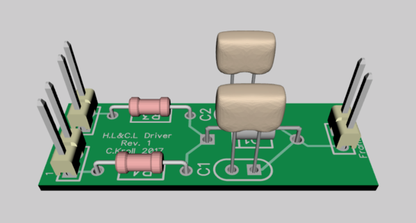
Thanks GRJ, I'm slowly working on the personable library parts. I toyed around with diptrace after doing a small proto-type board just for the diode and caps and wanted to make it simpler for when i do the next set of Budd car upgrades. (Have to be careful club members are seeing the results and wanting me to do upgrades for them ![]() ) I created this board and think it fits the KISS statement.
) I created this board and think it fits the KISS statement. 
Frame GRD is at the right end of the board. Pins 2&3 go to the ERR board and to both wires noted as black in your diagram above. Pin 1 is set with the 1k resistor for the connection to the pair of R/G LED's. Pin 4 is set with the 220ohm resistor for the F.HL or B.HL which ever unit it is.
-Chris


