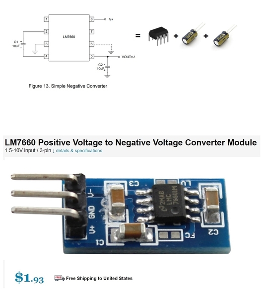
And for the sake of completeness, I was surprised to find the 7660 voltage inverter IC chip is still alive and kicking! This is one of those chips like the 555-timer IC chip that has been around forever.
With the 7660 which came as an 8-pin DIP (like the 555), you simply add 2 inexpensive capacitors and you have a positive-to-negative voltage inverter. So put 5V DC in, you get -5V DC out. Put 4.5V DC in, you get -4.5V DC out. It uses so-called charge-pump or switch-capacitor (NO inductors/coils) design and cannot deliver a lot of power but plenty for driving the -5V for the yellow wire output.
I see you can even buy a 3-pin module. Though with the simplicity of the circuit, if soldering up a circuit anyway, this might be one of those unusual situations where you can build it cheaper from parts than you can buy the completed Asia module! ![]()
Again, this addresses the limited interpretation of the OP's question as to how to generate -5V (along with +5V) to drive the yellow-wire. So summarizing:
1. 5V wall-wart with DPDT switch to flip the polarity
2. Half-wave rectified AC with a -5V regulator IC chip
3. Three 1.5V batteries with a switch to flip the polarity
4. Boost step-up switch-mode converter generating +/- outputs
5. DC-DC isolated converter, + of floating DC output tied to common
6. Charge-pump switched-cap voltage inverter
7. Use an actual FasTrack switch
I think we've got this one covered. 


