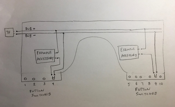
As I mentioned in the previous post, there is a wiring set dedicated to the operating accessories. A basic illustration and explanation is in order.
First, I cut 2 wires the length of the table from left to right. On the left, they are connected to the track power posts on the same CW-80 transformer. I wanted to be able to adjust the power to affect the brightness of some of the lights and the speed of motion on some of the accessories. On the right side, the wires are not connected to anything. Then, for each accessory, I created a path for electricity to move from the (+) bus wire to a push button switch, then continuing from the switch to one terminal on the operating accessory, then continuing from the other accessory terminal to the final destination of the (-) bus wire. That was the general thought process. Each accessory was connected and tested. Some accessories were that simple. Others had additional features which required additional wiring. There are 10 button switches. I also had two other accessories (arch bridge with lights and billboard with lights) that were connected directly to the bus. When the transformer power was on, those accessories were lighted. The bridge lights were a helpful indicator to me if the transformer power was on or off.


