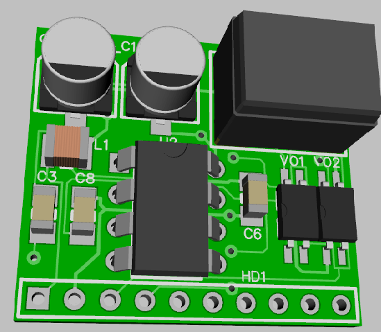
You can generate holes of any size easily and save them as a pattern. You number the pads and then use the component editor to connect them to the pattern. Finally, you drop in the 3D representation of the part and make it match up to the pattern. On my Super-Chuffer 3D image, I didn't have any representation for the 1/2A switching power supply module in the upper right, so I just grabbed a likely looking square component with three leads and massaged it into something that was the size of the power module. It's really useful to be able to visualize what the populated board will look like before you go to press, saves a lot of "oops" runs. ![]()