


Consolidated Leo posted:I got it now. I knew you guys would be able to straighten me out.
Here's my first sample:
Looking good.
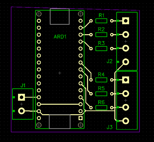
If J1 is used for your supply power, then + should go to VIn (Pin 30) and not +5V (Pin 27 as shown on your diagram. ) Also, I would put a diode in between the + of J1 and pin 30, just for those oops moments.
