I did a search and found the following post with what I believe are the aforementioned notes.
https://ogrforum.ogaugerr.com/t...48#48874849343058248
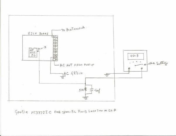
I took the liberty of copying the key diagram:
I agree with Dale's comment about using the meter's Current measurement mode. The Harbor Freight meter probably uses a 1k Ohm burden resistor for the 200uA range. So as Dale says, this swamps out the 51k resistor and you are left with a 1k Ohm load and a voltmeter. In any event this answers my earlier question of the scale when below 30 is bad, above 40 is good. The meter could have been in the Voltage measurement mode without the 1k resistor swamping out the 51k resistor.
The technical considerations get somewhat bogged down with the filtering effect of the 0.1uF capacitor when there's a 1k vs. 51k Ohm parallel resistor and how this plays off with the integrating algorithm of most hobby-grade voltmeters.
Bottom line is to simply make note of what measurement setup you're using so numbers from different set-ups can be normalized/compared. I believe that if/when GRJ or JGL implement their wireless transponding signal-strength system, it will measure voltage (not current) as that's what the Arduino can do directly.


