


rad400 posted:Attached are the plans for the 455kHZ earth ground signal car meter. The signal car meter consists of a 51K resistor, .1uf cap & a R2LC radio board which I mounted on an old dummy engine with pickups. Also used a Harbor Freight free-be meter on the 200 u amp range. The trickiest part of this build, was to solder a wire to pin 13 of the MC3372IC, which is located on the R2LC board. See the attachments for the schematic, R2LC board pin assignments, MC3372IN spec sheet.
Also attached a summary sheet that Chris Lord of our team but together, on all the items we learned from talking to Lionel's CTO group when we were doing our testing of the TMCC/Legacy signal.
Thanks to OGR forum member Gary Emmich for investigating on how to use the R2LC radio board to measure signal strength.
Hope this helps,
Bob D
NJ-HI Railers
Adding additional information:
The red connector next to the meter is a connection point to test different types of antennas which could be used in your engines to improve signal strength. I used the four wooden poles at the corners of the engine, to wrap wire/foil around during testing.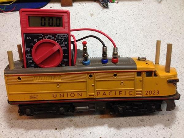
The second photo provides a top view of the connections to the R2LC board
Bob D
NJ-HI Railers


