


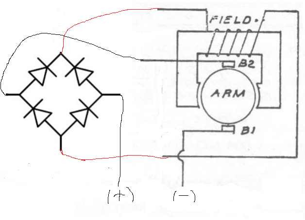
The diagram is correct, it is just not labeled well.
The black leads to the rectifier are connected to the ~ & ~(it doesn't matter which).
The red leads from the field to the rectifier are connected to the + & -(again, it doesn't matter which).
The connections marked "+ & -" at the bottom are the motor leads - connected to the PS1 motor output.
If the loco starts in the wrong direction, switch either the red leads or the "+ & -" connections.
