A number of topics on the forum have talked about the above readily available power supplies. They are nicely laid out, fairly compact and quite affordable; available in 5 amp or 10 amp versions. They are offered by several sellers on ebay and Amazon amongst others. They are both voltage or current controlled, and have a built in voltmeter and ammeter. Also they are fan cooled. As handy as they are, they all have one major drawback that can bite you hard if you don't follow the proper startup procedure. And that is if you inadvertently hookup the load first, then turn it on; POOF, its shot. (Don't ask me how I know this. ![]() ) The manual has this prophetic statement (if you read manuals) on page 1: "Do not connect any load to the power supply before it's turned on", followed by "Likewise make sure to disconnect the load before shutting down the power supply." All well and good as long as you read the manual and you happen to remember this.
) The manual has this prophetic statement (if you read manuals) on page 1: "Do not connect any load to the power supply before it's turned on", followed by "Likewise make sure to disconnect the load before shutting down the power supply." All well and good as long as you read the manual and you happen to remember this.
In January I bought a 10 amp one (replacement for my first one!) and got to thinking about a fail safe method to prevent disaster. I collaborated with my good friend rtr12 (Tom) who has experience from his working career with latching relays. After a few discussions we came up with the following circuit:
The idea is that even when you physically connect the load to the PS, it won't be powered up until you turn the power on (which also powers up the wallwart relay power source), then push the NO Connect pushbutton. This energizes the relay. The first set of contacts closes to "latch" the relay on, and the second set puts power to the load. The relay remains energized until you push the NC Disconnect pushbutton, or there is a loss of power. Then the relay opens, disconnecting the load.
A second advantage is that if you experience a power blip while using the PS, the relay immediately opens, and when the power is restored there is no connected load (and no "POOF"). I have also found it very handy to be able to connect and disconnect power to the load using the pushbuttons instead of inserting and removing banana plugs. But that's just me.
It's easy to build using mostly parts in your surplus bins. You need a 12vdc DPDT relay good for 10 amps (if a 5 amp PS) or 15 amps for the 10 amp version. You need a surplus 12vdc wallwart (any output of 200 ma or more), and either two ON-(ON) pushbuttons, or one each of NO and NC.
As seen below I have hot glued the main components to a small chunk of mapboard, and pre-wired most of it. Most any standard DPDT 12vdc relay will work. I chose this one simply because I have several on hand doing nothing, and it has contacts rated at 15 amps. ( I think I bought them from Dale Holzman a number of years back)
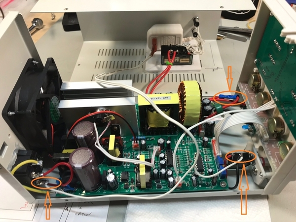
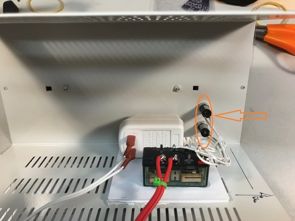
Here I have connected the wallwart power wires to the inlet power receptacle and the power switch such that the wallwart is powered with the main switch. Note the near orange elipses. Also note the red power wires connected in the far orange elipse. I chose to unsolder the original red wire from the outlet connection board, and splice it to the wire to the relay. Then the other wire from the relay is soldered to the original outlet board connection. Simple!
This view shows the map board hot glued in place and the pushbutton switches installed in the top of the cover (orange).
This view is the finished top cover with the new switches marked according to function. I chose to mount the switches on top because there is not much open space anywhere on the front panel of the PS. This location has turned out to be very handy and not in the way of anything else.
And so the acid test. Like a charm she works! Here we are powering two auto type headlamp bulbs that pull about 4.5 amps each at 14.2vdc (lamps are not in the picture). The max current I was able to pull was 9.89 on the ammeter. Not bad; close enough to 10 amps for me. The fan was moving lots of air meanwhile.
That's about it. Any questions or comments; shoot. It's a fairly simple 2 or 3 hour project once you have the parts rounded up. Since all the parts I used came from my spare parts bins, there was no real out-of-pocket expense involved. YMMV. I am loads happier using this little guy now. And more confident that I won't fritze it! ![]() I really need to offer my thanks to rtr12 for all his help and expertise on wiring the relay to work for this purpose. Thanks Tom!
I really need to offer my thanks to rtr12 for all his help and expertise on wiring the relay to work for this purpose. Thanks Tom!
Rod


