I hung a scope on my P/S, mine is the typical 10A 30V model, probably identical to yours. The startup spike is scary, so that needs to be addressed. The shutdown doesn't really pose a problem, at least with a sample of one. That being the case, I decided to address the startup issue. Also, the relay drops out pretty quickly, and it appears it's turned off before the power supply caps discharge and let it drop out of regulation.
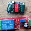
I looked around the shop and discovered I had all the raw materials in hand. On top is a mini 120V to 12V isolated power supply. On the bottom is a 0-10 second delay turn-on module. Looks right!
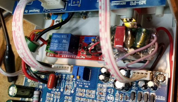
I didn't bother with a diagram as this was dirt simple. I connected the 120V power primary after the power switch, and connected it's 12VDC output to the VCC of the timer module, observing polarity of course. Then the timer module was simply inserted into the positive lead of the power supply going to the binding posts using the COMMON and N/O contacts. The timer was set for about a 2 second delay, that was after the power had stabilized at any voltage output setting.
In order to be safe here, I shrink-wrapped the 120V power supply in clear plastic, then it was stuck on top of the power switch. The timer module is stuck to the case with the same Double-Sided foam tape.


