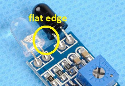
In this eBay photo, the flat edges of both devices seem to be on the inside. Why not power up a working module and measure the the polarity of the DC voltage across each device. Then note whether the flat edge is + or - for each device.
As cjack suggests, if you place the edge of the iron across the 2 blobs of solder on the back side then in, say, 5 seconds you should be able to gently pull the part out.
I suggest determining polarity using above method first. There's always a chance that you damage a part during removal and determining polarity on a damaged part can be frustating. Note that the detector is actually a transistor and not a diode so the 2 pins on the black-lens phototransistor are referred to as collector/emitter (rather than anode/cathode).
Oh! Good advice about checking polarity on the flat side of the sensor I see. It looks like in that circuit the round side of the sensor is connected to the common (ground) side of the circuit. These sensors are sometimes photo transistors and sometimes diodes. Sometimes with three leads and sometimes two. I don't know all there is to know about them, obviously, except that if you shine light on a pn junction, current will flow thru the biased junction, or a voltage will develop across the junction. So the circuit can vary.
Probably just note where the flat side is connected and maintain that orientation in the rewired circuit.


