@Don Baird posted:...
re: the 153IR controllers
- in two of them the two left hand terminals are labeled A & U the four terminals on the right are labeled “AC power, AC ground, NO, & NC.”
- in third (1961 I believe) the two left hand terminals are labeled “power supply.” The four terminals on the right are labeled “Com 2, Com 1, NO, & NC”).
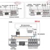
I was afraid of that. Unfortunately the mix of 153IR styles makes for a bit of legwork. Here's a "reference" diagram I've been working on with tidbits of info provided by other forum members when 153IR related issues arise. Hopefully we can confirm or add to the knowledge base. Not all of the diagram applies to your situation but my comments will be to the point.
Apparently you have two (2) of the upper right version identified as 2002 above...and one (1) of the upper left version identified as 2001.
What I need to confirm is these early versions can operate on DC voltage (as does the later version identified 2014). These need to operate on DC voltage as that's what is coming from the AC-to-DC converter module set to 10V DC.
1. Set the Power Selection toggle switch to the AUX POWER position.
2. One 153IR at a time, apply 10V DC to the two power terminals on the left side of the 153IR. Get a pad of paper to take good notes. Apply +DC output for converter to the left (unmarked or A) power terminal and -DC from the converter to the right (unmarked or U) power terminal. There is NO power indicator, light or whatever on the 153IR to show power is "on". However, when you wave you hand in front of the 153IR you should hear the internal relay "click" on. When you remove your hand, after a few seconds you should hear the relay "click" off. You may never get any clicking action.
Whether you get the clicking relay or not, next swap the two 10V DC power wires. So now +DC goes to the right power terminal, and -DC to the left power terminal. Repeat the hand-waving to listen for the 153IR internal relay clicking on and off.
Report the results for the 6 experiments (2 experiments per 153IR).
@Don Baird posted:I am currently watching uTube videos about multimeters in order learn how to set the the voltage on the DCAC converter and check my track for continuity in my wiring.
Do you now feel comfortable using your multimeter to test for continuity? When you reach the point where you can touch the 2 meter probes to two different contact point and read the meter to determine continuity then here's more homework:
1. Confirm the 153IR Power Selection toggle switch is still in the AUX POWER position.
2. One 153IR at a time, test for continuity as follows:
Place one meter probe in the left power terminal (unmarked or "A" depending on version. if you have a needle or thin probe you ought to be able to insert it into the connector and 'clamp' it in place with the orange lever. Then take the other meter probe and one-by-one briefly touch each of the 4 terminals on the right side of the 153IR. So depending on the version, the 4 terminals are labeled left-to-right COM2, COM1, NO, NC...or... ACC PWR, ACC GND, NO, NC. Use the meter to determine if there's continuity for the 4 cases.
This will be enough information to tell me how to combine the 2 different styles of 153IR you have to work together as a team of 3.
Yes, I realize this seems quite tedious and time-consuming but I think all above can be done in maybe 30 minutes.


